This thread has been locked.

If you have a related question, please click the "Ask a related question" button in the top right corner. The newly created question will be automatically linked to this question.

TMUX1574: SPI aplication cascading 5 switches

Part Number: TMUX1574
Other Parts Discussed in Thread: SN74CB3Q3257, SN74CB3T3257, SN74CBTLV3257

Hi Sir,

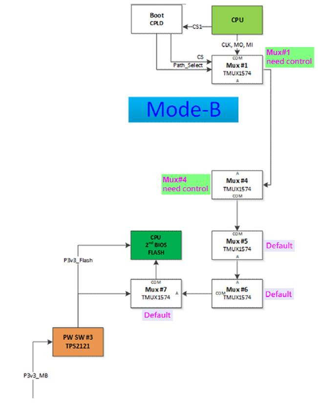
My customer is using 5 pcs TMUX1574 from CPU to SPI flash as below diagram,

And their SI team has concern about the signal integrity. So they have below questions and asking if there is any report or information on it.

Could you please help on it?

1.      After switching, how long can I be sure the signal is stable? (SEL pin set to high from low, or reversed)

2.      Does the ibis model (simulation model) provide unstable condition?

3.      For SPI application, our SPI FLASH is operation on 50MHz with dual SPI.

4.      Waveform amplitude @ 50MHz after 5 TMUX1574

  • Hello,

    What is your need for cascading five TMUX1574?

    • The switching time is provided in the datasheet as Ttran, which is the time required for the output to rise or fall as a result of a change in the SEL input. According to the datasheet, the typical transition time is 160 ns.
    • Instead of using the IBIS model (which is designed for simulating buffer devices and does not best represent the signal path of passive devices, such as TMUX1574), I recommend using the s-parameter model, which is available in the design & development tab on the product page.
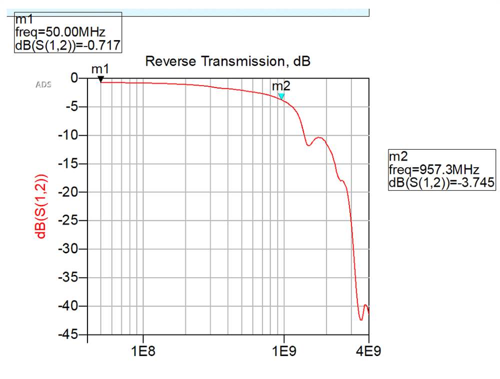
    • You can use the s-parameter model to simulate the response of five cascaded TMUX1574 and ensure that 50MHz is within the band of the frequency response. The 3dB point of this simulation is shown in the figure.
    • You can use the insertion loss parameter in the datasheet to estimate the attenuation. You can also use the s-parameter model. Using the s-parameter model to cascade five TMUX1574, you can measure the attenuation at 50MHz, which is approximately 0.71dB as shown in the figure below:

    Regards,

    Kate

  • Hi Kate,

    Thanks for your feedback.

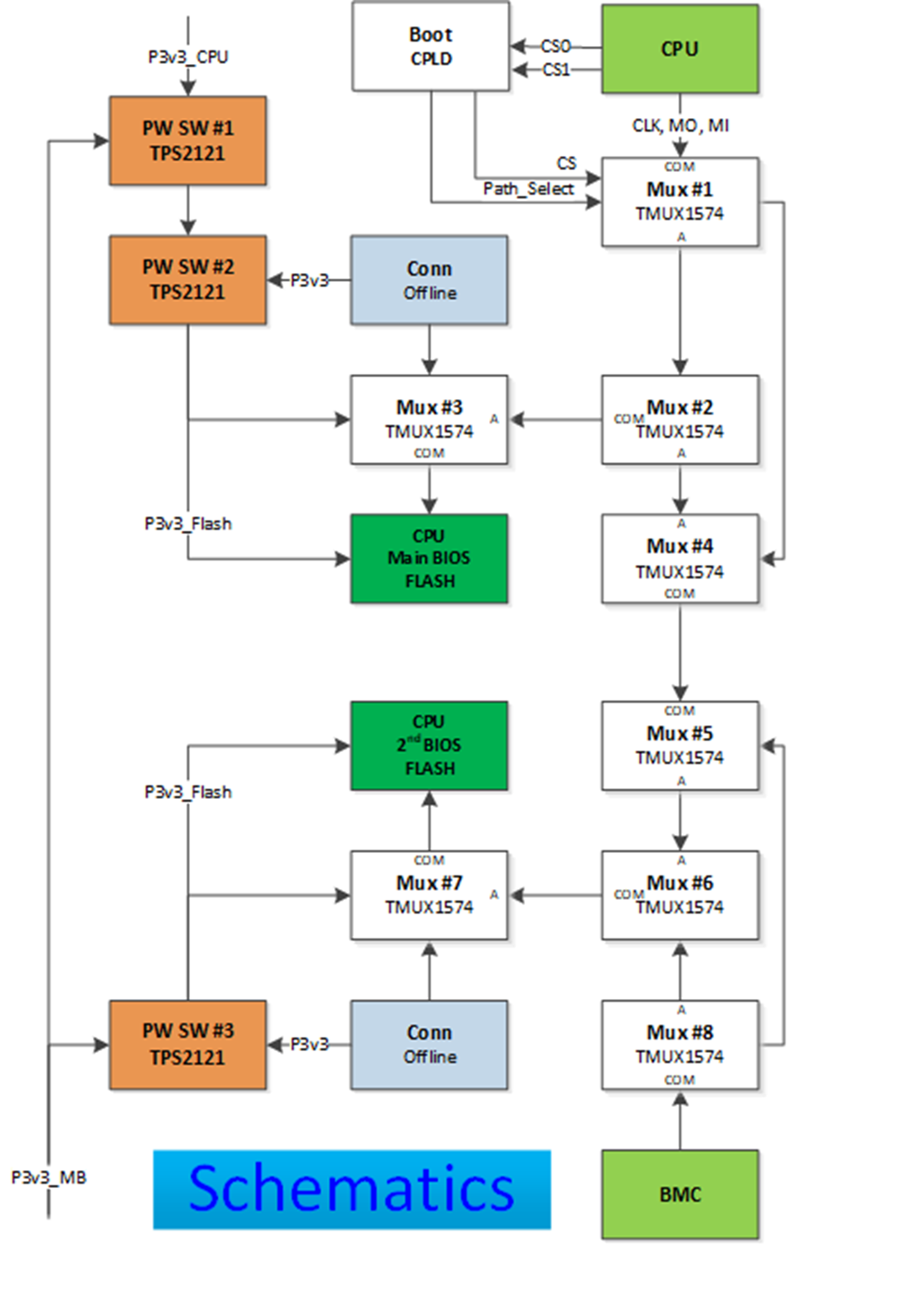
    Below is the more details diagram for the whole architecture about the MUX usage.
    We have 2 CPU, one is CPU, and another one is BCM.
    CPU boot need thru main BIOS to get boot code
    If CPU read data from Main BIOS fail, we will switch the access path to 2nd BIOS.
    And why we need BMC, it’s we will use BMC to recovery CPU’s BIOS code.
    Based on 2 CPU to access 2 BIOS path.
    So, you can see the long distance is 4pcs for without offline connector. 5pcs for with offline connector.
    Example:
    CPU access 2nd BIOS (w/ offline programming connector as below:
    Mxu#1 => #4, #5, #6, #7 > 2nd BIOS.

    From my customer's experience before, if the data rate under 30MHz and less 2 MUX to switch 2 SPI Flash is fine.
    Over 2 Mux or over 30MHz, the CPU may cannot read code from SPI FLASH.

    So my customer is concern about below items after cascade 5 MUXs.
    1.      waveform amplitude
    2.      driving current
    3.      Access frequency.

    If TMUX1547 is not a suitable part for this kind of design.
    Could you please help to compare below mux signal work in same condition(cascade 5 mux with 50MHz)?
    TMUX1574 vs 74CB3Q3257, 74CV3T3257 and 74CBTLV3257

    Because customer had cascade 2pcs mux with 12-inch routing and operating with 74CBTLV3257 at 25MHz is working well.

    In my understanding how to select the correct MUX is:
    1.      Ron impedance need lower
    2.      Support bandwidth
    3.      C-load
    4.      R-load
    5.      Select to data path operation delay
    6.      Signal rising/falling time

  • Hi Anne,

    • Have you tried simulating 5 cascaded muxes with the TMUX1574 s-parameter model? According to my results (as shown in the figure in my previous reply), you may expect approximately 0.71dB of attenuation of the amplitude at 50MHz for five series TMUX1574, which should not be a significant amount of attenuation.
    • Driving current is determined by what is driving your system. The maximum continuous current of TMUX1574 is +/-25mA and should not be affected by multiple TMUX1574 in series.
    • What are you referring to by "access frequency"? As you can see in the figure in my previous reply, the bandwidth of five TMUX1574 in series is approximately 1GHz. This should provide plenty of margin for your application at 50MHz.
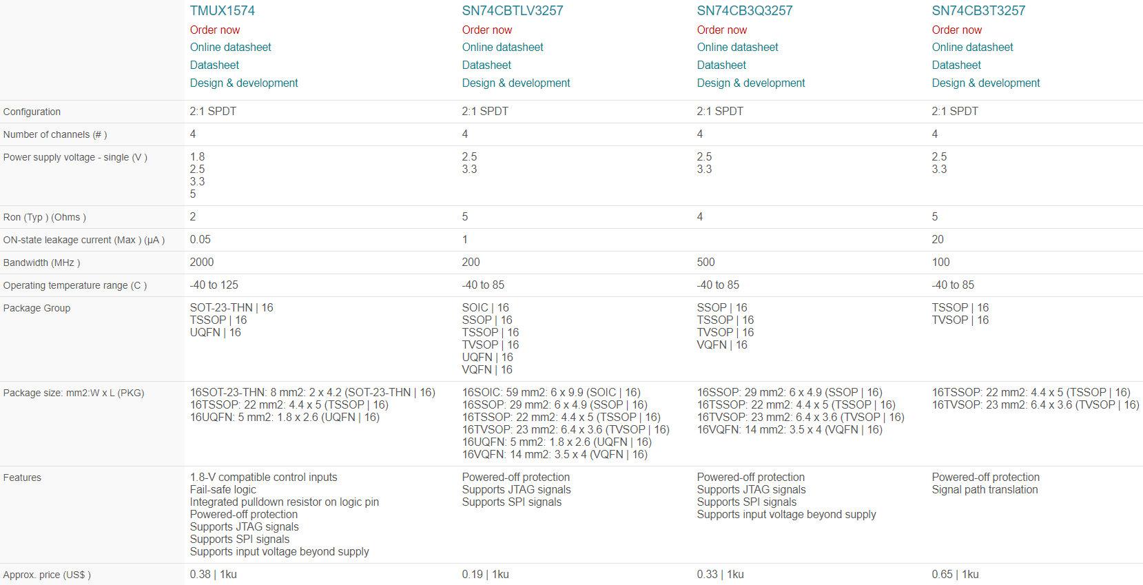
    • I have provided the parametric comparison of TMUX1574, SN74CB3Q3257, SN74CB3T3257, and SN74CBTLV3257 below. As you can see:
      • Ron of TMUX1574 is the lowest. You can expect Ron of each device to add in series in your application.
      • Bandwidth of TMUX1574 is highest. As I mentioned before, five TMUX1574 in series results in an approximate bandwidth of 1GHz, which is higher than the other SN74 devices.

    • The capacitance and resistance loads of TMUX1574 should not be significant compared to the parasitic loads of the board traces.
    • Ttran is the time required for the output to rise or fall as a result of a change in the SEL input. According to the datasheet, the typical transition time of TMUX1574 is 160ns. System level transition time is dependent on the RC time constant of your system. As I mentioned earlier, this should not be significantly impacted by the series muxes themselves compared to the other loads/parasitics of your system.
    • You can expect the propagation delay to add with each device in series. For the worst case estimate, you can multiply the maximum characterized propagation delay by five. Propagation delay is mostly dependent on the package of the IC (due to the length of the bond wires and leads). Worst case, propagation delay of TMUX1574 may be approximately 500ps.


    I recommend using TMUX1574 compared to the other SN74 devices you mentioned. Check out the s-parameter model for TMUX1574 to simulate measurements, such as bandwidth, for this application!

    Regards,

    Kate