This thread has been locked.

If you have a related question, please click the "Ask a related question" button in the top right corner. The newly created question will be automatically linked to this question.

SN74CBT3251: NTC issue with SN74CBT3251

Part Number: SN74CBT3251

Hi Experts;

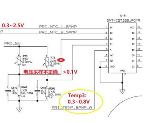
I have questions on the SN74CBT3251, please the schematic below,

The B2 and B1 is input the voltage signal generated by the resistor divider, the output (A port) is connect to the input of the ADC (high impedance input) .

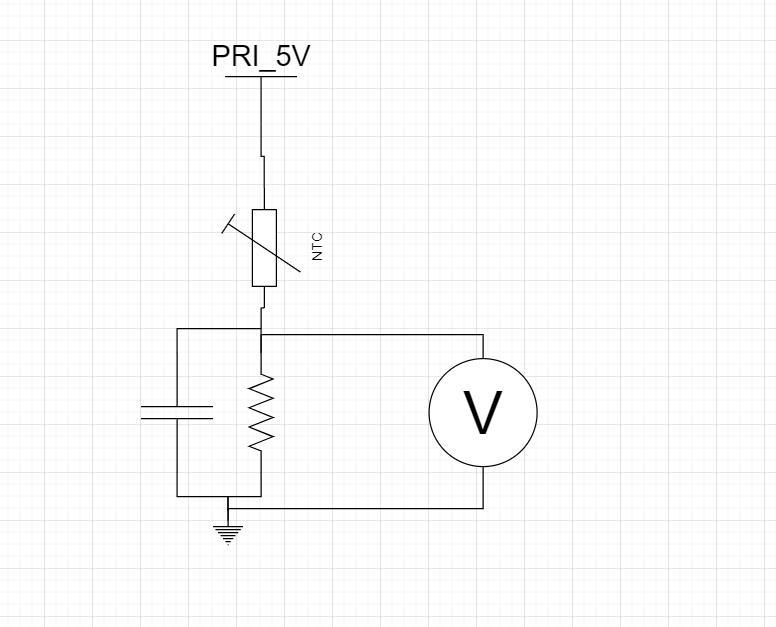
Normally, the right voltage on the B port is 0.3V ~ 3V (divided by NTC and resistor) .

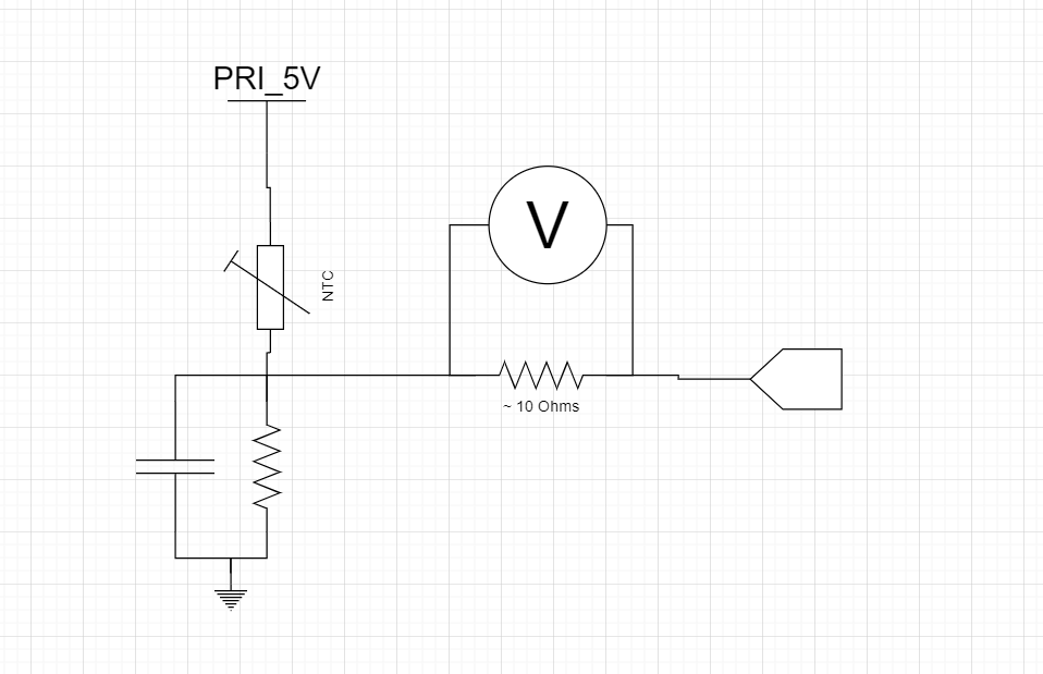
1)  When the divided voltage is input to the SN74CBT3251 , the voltage will be lower than the 0.1V, we disconnect the A port to the external load,

the issue is still there.

Could you please help on it?

  • Hi Jason,

    I want to confirm a few things first to make sure I understand everything.

    1. What is the voltage at the B port and A port? If you have a scope shot of those waveform's it would be helpful.
    2. What are the voltage readings on the select pins?
    3. Also have you been able to replicate the problem on another board?

    It sounds like the switch is in a high impedance state always, so I think there could be something with the select pins.

    Best Regards,

    Parker Dodson

  • Hi  Parker:

    Thanks for your reply.

    1. The B port is 0.1V and the A port i need to clarify 

    2, i will check ,do you mean customer didn't turn on the B1 or  B2 port could cause this issue? 

    3. Customer tested 4 pcs of board, one board has no issue, one board has the issue on B1 but B2 is Ok, one board has the issue on both of the B port.

  • Hi Jason,

    1. If the input voltage (channel B) is at 0.1V I am unsure what the problem is, the MUX will not change the input voltage, that is dependent on the NTC divider voltage We have an application note on Monitoring an NTC/Resistor Divider here
    2. I wanted to check to make sure the right channels are being selected, more so a sanity check to make sure this *isn't* the issue, I am not sure if that is the issue, but it is an easy enough test to check quickly.
    3. What is the exact customer problem? I thought it was that Port B was higher than what was being read at port A. However by your reply it seems like the voltage going into the MUX is low (<100mV), so I am having a hard time seeing the exact issue, I apologize for the inconvenience, but I want to make sure I am working on the same problem that I think you are.

    Best,

    Parker 

  • Hi Parker:

    Sorry to make you trouble.

    The exact issue is the B port voltage is below than 0.1V which is much lower than the reasonable NTC divided voltage. 

  • Hi Jason,

    I am sorry for the confusion!

    To start to narrow down the source of the problem the first thing is to disconnect the IC. Then measure the voltage drop to ground from the NTC resistor bridge, without the IC. If there are loading effects caused by the IC, they won't show up in this configuration, shown below:

    If the divider acts as expected the next test would be to implement the following circuit to see if the loading of the ADC is causing issues:


    We measure the drop across the 10 Ohm (or similarly sized resistor) to see if the ADC + resistance is causing any loading effects. Even though the ADC is supposed to be high impedance, I just want to make sure that it isn't causing any errors. 

    For these tests it is important that they are carried out on the boards that are failing; if the problem is solved after removing the IC and running the above tests, then it is much more likely that the mux is the culprit behind the failure. 

    Please let me know if you have any questions or concerns about the above tests.

    Thanks

    Parker Dodson