This thread has been locked.

If you have a related question, please click the "Ask a related question" button in the top right corner. The newly created question will be automatically linked to this question.

Some questions regarding USB-C...

Not sure if this is the right forum to post, but I have a customer considering some TI devices related to a USB-C project they are working on.

He had some general questions regarding USB-C protocol / implementation, and I was hoping somebody would be able to help provide some insight on these...

The basic flow the engineer has in mind related to working with USB-C is as follows:

  1. A USB Type-C cable is connected
  2. The CC pins are used to detect connection/direction
  3. Based on the state of the CC pins,
    the controller communicates with the plugged-in USB-C device and E-Marker chip.
  4. Then decides the power/current/direction
  5. Power is supplied from the source to the sink (this is when voltage is actually applied to Vbus)
  6. Opens up communication lines to start talking between devices


If something caused 1~3 above to have issues, neither power delivery or communication would occur?

If something caused 1~4 above to have issues, power delivery would occur, but not communication?


This was the first time I heard USB-C cables can have an E-Marker chip inside them…and I have been trying to research this, but was hoping somebody more experienced could give their thoughts on the above flow.

Regards,

Darren

  • Hi Darren,

    The flow is close, but does not mention a Type-C non-PD device. You can find the updated flow below

    1. A USB Type-C cable is connected
    2. The CC pins are used to detect connection/direction
    3. The Type-C source detects that a sink device has been connected and enables 5V on VBUS
      1. As defined by the Type-C spec, a Source shall present a pullup resistor on the CC pins (Rp) and a sink shall present a pull down resistor on the CC pins (Rd)
      2. When the Source detects an Rd, it know that a Type-C sink has been connected and enables 5V on VBUS
    4. Once the implicit 5V contract has been negotiated, if the source or sink devices are capable of power delivery, they begin sending PD messages on the CC pins
      1. First communicating to the e marker in the cable
      2. then to the connected device
    5. The two devices then negotiate a PD power contract
      1. Can do a power role swap if needed
      2. Or keep power roles from implicit 5V contract and negotiate a higher voltage
    6. Power is supplied from the source to the sink (this is when voltage is actually applied to Vbus)
    7. The PD controllers then negotiate alternate modes if both support an alternate mode such as DisplayPort

    As for the two questions, below are the answers for both

    If something caused 1~3 above to have issues, neither power delivery or communication would occur?

    • Correct. If a device is never attached, or if the Rp/Rd is never negotiated, then 5V will never be presented on VBUS and the PD controller will not know to move onto PD communication.

    If something caused 1~4 above to have issues, power delivery would occur, but not communication?

    • I'm not sure what you mean by "communication". I'm going to assume data transfer. All the PD controller does is negotiate the implicit voltage contract, negotiate a PD power contract if both devices are PD capable, and negotiate an alternate mode if both devices are capable of alternate modes. You can have power role swaps and data role swaps if needed but this is the basic idea. 

    One thing to note is that only Type-C PD allows for you to have a data role different than your power role. For example, for a USB Type -C device, it is either a Source DFP or Sink UFP. Type-C PD allows for your system to act as a Source UFP or Sink DFP based on a power role swap or data role swap command

  • Hi Adam, 

    I appreciate the detailed descriptions.

    The engineer has come back with some follow-up questions I was hoping you could help with?

    When does USB data communication (USB2.0 D+/D-) actually begin?
    - After PD negotiation has completed, and voltage is applied to VBUS?
    - In other words, there is no communication before VBUS is applied, correct?

    Also, regarding the Power Role Swap from the above reply...
    - If the PD Controller is setup to initiate a Power Role Swap directly after connection is detected (device powers the host), the host never provides power to the device first, correct? (That is, before 5V is applied on VBUS, the Power Role Swap happens)

    Thanks,

    Darren

  • Hi Darren,

    Here are answers to the customers question

    When does USB data communication (USB2.0 D+/D-) actually begin?

    • USB detection/communication should not begin until after VBUS has been applied 

    If the PD Controller is setup to initiate a Power Role Swap directly after connection is detected (device powers the host), the host never provides power to the device first, correct? (That is, before 5V is applied on VBUS, the Power Role Swap happens)

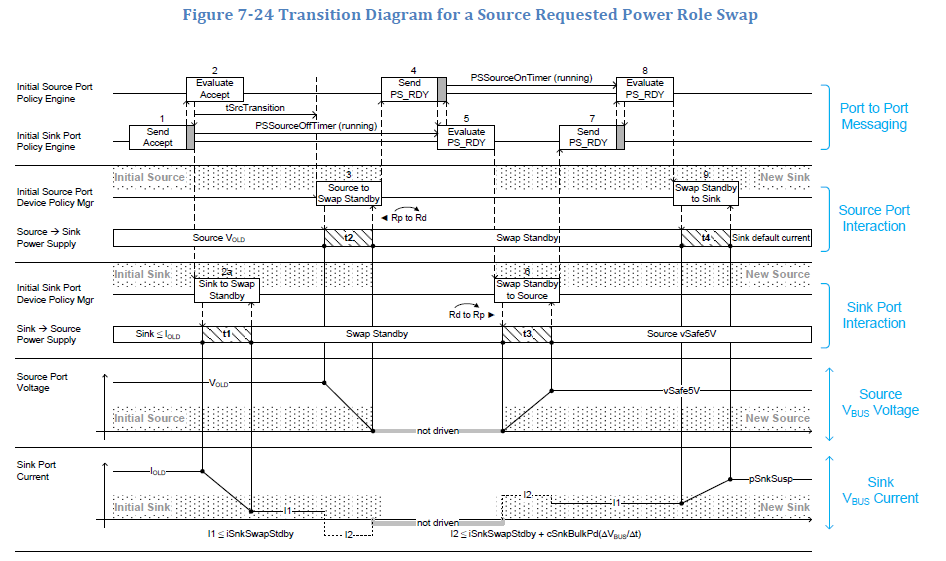
    • False, a power role swap occurs after the initial 5V connection has been made. Below is a screenshot from the USB Type-C PD spec giving an example of what the message sequence should look like for a Source initiating a power role swap
    • You can see in the row labeled "Source Port Voltage", that there is a initial voltage on VBUS from the old source, and then a transition where the new source is supplying 5V to VBUS

    Step Initial Source Port -> New Sink Port Initial Sink Port -> New Source Port
    1 Policy Engine receives the Accept Message. Policy Engine sends the Accept Message to the Initial Source.
    2 Protocol Layer receives the GoodCRC Message from the Sink. The Policy Engine tells the Device Policy Manager to instruct the power supply to modify its output power. Protocol Layer receives the GoodCRC Message from the Initial Source. Policy Engine starts the PSSourceOffTimer.
    2a The Policy Engine tells the Device Policy Manager to instruct the power supply to transition to Swap Standby. The power supply Shall complete the transition to Swap Standby within tSnkStdby (t1); t1 Shall complete before tSrcTransition. The Sink Shall Not violate the transient load behavior defined in Section 7.2.6 while transitioning to and operating at the new power level. Policy Engine starts PSSourceOffTimer. When in Sink Standby the Initial Sink Shall Not draw more than iSnkSwapStdby (I1).
    3 tSrcTransition after the GoodCRC Message was received the power supply starts to change its output power capability to Swap Standby (see Section 7.1.10). The power supply Shall complete the transition to Swap Standby within tSrcSwapStdby (t2). The power supply informs the Device Policy Manager that it is ready to operate as the new Sink. The CC termination is changed from Rp to Rd (see [USB Type-C 1.2]). The power supply status is passed to the Policy Engine.
    4 The Policy Engine sends the PS_RDY Message to the soon to be new Source. Policy Engine receives the PS_RDY Message and stops the PSSourceOffTimer.
    5 Protocol Layer receives the GoodCRC Message from the soon to be new Source. Policy Engine starts the PSSourceOnTimer. At this point the Initial Source is ready to be the new Sink. Protocol Layer sends the GoodCRC Message to the new Sink. Upon evaluating the PS_RDY Message the Initial Sink is ready to operate as the new Source. Policy Engine tells the Device Policy to instruct the power supply to operate as the new Source.
    6 The CC termination is changed from Rd to Rp (see [USB Type-C 1.2]). The power supply as the new Source transitions from Swap Standby to sourcing default vSafe5V within tNewSrc (t3). The power supply informs the Device Policy Manager that it is operating as the new Source.
    7 Policy Engine receives the PS_RDY Message and stops the PSSourceOnTimer. Device Policy Manager informs the Policy Engine the power supply is ready and the Policy Engine sends the PS_RDY Message to the new Sink.
    8

    Protocol Layer sends the GoodCRC Message to the new Source.
    Policy Engine evaluates the PS_RDY Message from the new Source and tells the Device Policy Manager to instruct the power supply to draw current as the new Sink.

    Protocol Layer receives the GoodCRC Message from the new Sink.
    9 The power supply as the new Sink transitions from Swap Standby to drawing pSnkSusp within tNewSnk (t4). The power supply informs the Device Policy Manager that it is operating as the new Sink. At this point subsequent negotiations between the new Source and the new Sink May proceed as normal. The new Sink Shall Not violate the transient load behavior defined in Section 7.2.6 while transitioning to and operating at the new power level. The time duration (t4) depends on the magnitude of the load change.
  • Hi Adam,

    I appreciate the level of detail in the reply. Sorry this response has been delayed.

    Your comment:
    You can see in the row labeled "Source Port Voltage", that there is a initial voltage on VBUS from the old source, and then a transition where the new source is supplying 5V to VBUS

    From SLVAE65:

    "TPS6598x supports booting from no-battery or dead-battery conditions by receiving power from VBUS."

    The customer is asking if the PD controller was set for dead-battery operation, but the tablet was completely drained, it can't be charged?

    From my understanding, there are two use cases.

    The first is TPS6598x PD controller is in some other machine external to the tablet, and receives power from some equipment, and when a dead-battery tablet is connected, it can setup PD to charge the dead tablet, right? This doesn't need the "dead-battery" setting to function, yes?

    The second is, the TPS6598x PD controller is inside the tablet, and receives power from the tablet. If the tablet is completely drained, then it can't receive power the normal way, and needs to be setup to receive power from VBUS.

    I think they are trying to ask that if the tablet has no power, and cannot provide power via VBUS (because it is drained), the PD controller won't start up, and will never direct power to charge the tablet. If my above understanding is correct, I don't think this is the case...

    I would appreciate your advice.

    Thanks,

    Darren

  • Closing this thread based on conversations over the phone