A related question is a question created from another question. When the related question is created, it will be automatically linked to the original question.
If you have a related question, please click the "Ask a related question" button in the top right corner. The newly created question will be automatically linked to this question.
It looks like the only application for the TS3A226AEYFFR is in the autonomous audio headset switch for CTIA/OMTP according to the schematic that was sent.
VDD should be within supply range of 2.6 V – 4.7 V according to the datasheet.
GND, GNDA, GNDB seem like they are wired correctly.
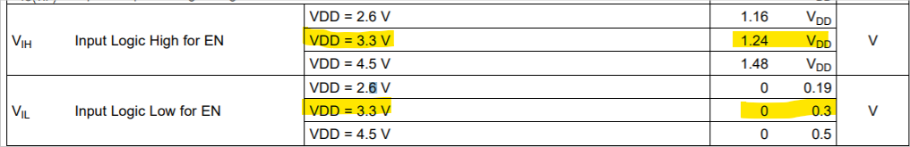
EN pin should be good as long as VIH and VIL specs are followed accordingly to your supply voltage.
The voltage levels for the TIP, MICp, Sleeve, and Ring, must be in compliance with the recommended operating conditions:
I take it that the DUT_HP_L input off of C2 sees 5-18V. Just make sure that it follows the VIO voltage for the TIP. Same goes for I/O’s HS_MIC, HS_MIC_EN, and HP_SENSE. Choose the current limiting resistors accordingly.
If there a specific part of the circuit that has a concern, please let me know!