This thread has been locked.

If you have a related question, please click the "Ask a related question" button in the top right corner. The newly created question will be automatically linked to this question.

SN74CBTLV3257: B side termination

Part Number: SN74CBTLV3257

HI Expert,

I want to confirm about B side termination.

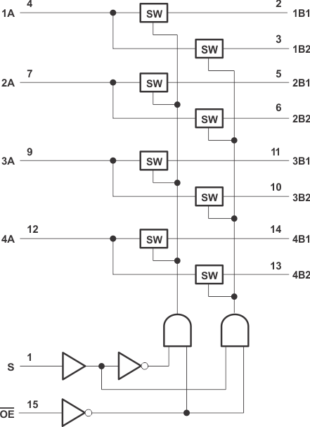
My customer is considering to use SN74CBTLV3257 for switching "Test mode" and "Production mode" for 4ch UART signals.

xB1 : Test mode

xB2 : Production mode

Can The xB1 pins terminate open at production mode(xA pins are always connected to B2, S=High)

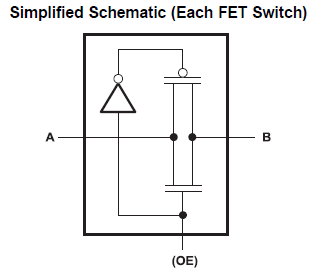
Also, Do you have the more detail of figure for Simplified Schematic (Each FET Switch)?

My customer is not quite sure about the diagram below.

Thanks

Muk

  • Each "SW" box in the functional block diagram is one such switch:

    Unused I/O pins can be left floating; see [FAQ] Frequently Asked Questions about signal switches and multiplexers.

  • Hi Yusuke,

    Can you elaborate a little more of this:

    "Can The xB1 pins terminate open at production mode(xA pins are always connected to B2, S=High)"

    When S = High xB2 will be connected to xA , xB1 pins will effectively be Hi-Z in this state.  Any unused signal pins should be connected to ground through a 50 Ohm resistor. If I am misunderstanding your question, please let me know so I can help find your answer.

    The Diagram that Clemens indicated shows the basic Multiplexer channel, while the switch you provided is what would go into each of the boxes labeled "SW". Each switch uses a transmission gate architecture, which is what you have attached to your question. This architecture allows the switch to pass analog signals with a lower Ron over the signal range than a normal N-FET switch. For digital signals it allows the capability to pass hard zeros and hard 1's because the switch utilizes both N and P Type MOSFET. 

    For more information please see our video on switch architecture

    Best,

    Parker Dodson

  • Hi Dodson-san,

    Customer is considering as below,

    Test mode : they use xB1 for software update for MCU by UART signals at test process. xB1 will be not used in production.

    The customer will change S pin to low, Then, MCU signal path will be change to dedicated test board. And, if Test is finished, this board will be removed connection.

    So, The production mode is use only xB2. And xB1 pins will be open.

    Customer want to terminate xB2 by open or pullup to Vcc. 

    As you mentioned, should the xB2 be connect to ground through a 50 Ohm resistor at this situation?

    Thanks

    Muk

  • Termination of unused I/O pins would matter only in high-speed applications. For slow digital signals like UART, you can simply leave it open, without any measurable effect. (And 50 Ω termination would conflict with the test mode; if you are paranoid enough to add a resistor, a 10 kΩ pullup would be fine.)

  • Hi Muk,

    As Clemens Indicated the termination is for higher speed applications, we recommend it  typically, but at UART speeds it shouldn't be an issue. And using a 10K pull-up to VCC would be okay in this instance as well. 

    Best,

    Parker Dodson