This thread has been locked.

If you have a related question, please click the "Ask a related question" button in the top right corner. The newly created question will be automatically linked to this question.

TS3DDR4000ZBAR short problem

Other Parts Discussed in Thread: TS3DDR4000

Dear Rami

As in was it previously soldered or was this probed initially out of packaging? If so what are the operating conditions? Could you probe the traces to see if there are any connectivity issues here?

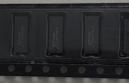
Ans:Assembly with taping stock.(peak reflow temperature : 220+/-5℃)

Additionally, how is the handling of the device being managed? Is any extra ESD protection such as a wrist strap being used?

Ans:We all wear anti-static wrist strap to work, the task was carried out on ATE machine with whole ESD protection.

Please have a reply.

Thanks~

  • Hi Daniel,

    Can you explain the tests performed before you observed the "short"? Can you describe the conditions of the testing environment? Stresses beyond those listed under Absolute Maximum Ratings may cause permanent damage to the device. Can you confirm that the layout guidelines in the datasheet were followed?

    Thanks,
    Kate

  • Dear Kate

    Have you reviewed the earlier post ?

    Can you explain the tests performed before you observed the "short"?

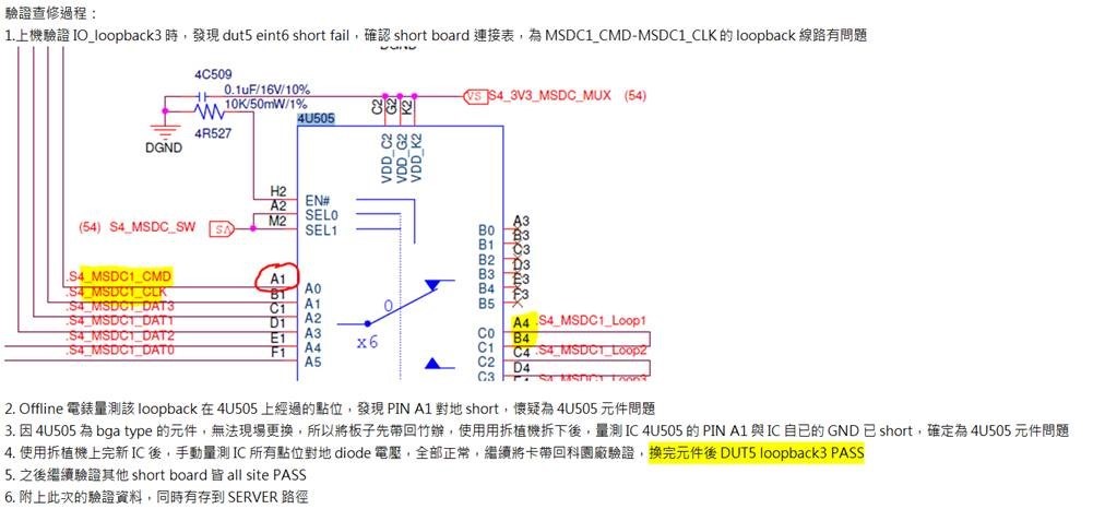
    Ans:As the attachment shows. Or you ask something others?

    Can you describe the conditions of the testing environment?

    Ans:Assembly with taping stock.(peak reflow temperature : 220+/-5℃)

    Stresses beyond those listed under Absolute Maximum Ratings may cause permanent damage to the device. Can you confirm that the layout guidelines in the datasheet were followed?

    Ans:Yes we followed the layout guidelines in the datasheet.

  • Hi Daniel,

    Thank you for providing this information again. 

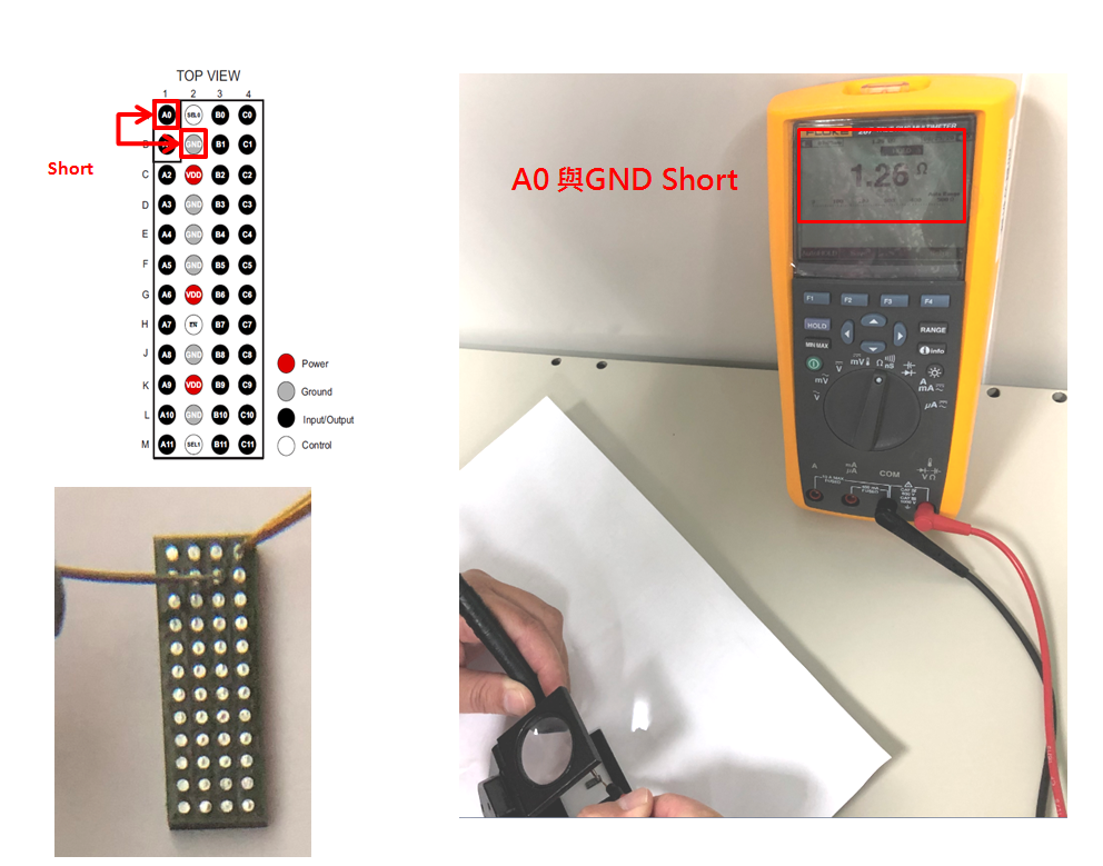
    This is your test condition: You are reading 1.26 ohm resistance when probing A0 to GND with a portable multimeter. The device is powered down VDD = 0V.

    TS3DDR4000 has the powered-off protection feature. This means that there is internal protection circuitry to protect the inputs and outputs and the power rail when the device is powered down.

    Image from datasheet table above shows low leakage current when device is powered down, the device has powered-off protection. 

    Multimeters such as this one have an internal battery that applies a voltage across the probes and measures the current to calculate the resistance.

    When you probe the input with this multimeter, you are applying a voltage to the input (VAO > 0V) while TS3DDR4000 has no power supply (VDD = 0V). Powered-off protection ensures that the switch's signal path is high impedance and that the power rail is not back-powered (no signal path to VDD). This internal protection circuitry provides a path for this multimeter voltage to GND to prevent damage to the signal path or power rail. This path is the resistance you have measured -- not a device "short problem". An actual short circuit will read a much lower resistance (such as touching the two probes together).

    Based on what you have provided, I do not see an issue.

    Best regards,
    Kate