This thread has been locked.

If you have a related question, please click the "Ask a related question" button in the top right corner. The newly created question will be automatically linked to this question.

TS5A3153: How to model the behavior of this device?

Part Number: TS5A3153

Good afternoon. I am developing a computer model of the device, which includes an analog switch TS5A3153. In order to develop this model, you need the SPICE model of this switch. Can you provide this SPICE model?

  • Hi Artem,

    Unfortunately we don't have a SPICE model for this part. That being said there are ways to approximate performance of the switch using passive circuitry and other modeling functions. 

    An On-Channel of the switch can be modeled as a RC filter with the R being the typical Ron and C being the C_On value.

    If there are other performance scenarios you would like to test please let me know.

    Best,

    Parker Dodson 

  • Good afternoon.

    In this case, can you tell us how to correctly calculate the capacity of an open analog switch? And how to correctly simulate the effect of temperature on this switch in this case?

    Thanks for the answer.

  • Hi Artem,

    For the open capacity - I think you are talking about the capacitance at the input when the switch is open. If that is the case you model the open pin as a capacitor that is connected to GND. You can also add a current source between the open switch pin and the output to model the leakage current. If this is not what you mean by open capacity could you please clarify, I am a bit unfamiliar with this term. 

    For temperature variations in the switch the two most notable effects are on On Resistance and leakage currents. To help simulate this a parametric analysis can be done where multiple values are cycled through during the simulation. Please see below for basic passive model for the simulation:

    Ron will change based on input voltage and temperature. You can try to simulate this by changing the input voltage and Ron through parametric sweeps or other choices. Leakage currents will mainly be affected by temperature as well , but as a note, the ID_off on the open channel will be smaller than what is spec'd because most of the leakage comes from the diodes, so the leakage you will see here is a very small leakage that goes over the high impedance of the switch, and in most cases can be negligible, but I left it in the model in case you wanted to use it. 

    The data you need you need to fill in the values can be found in the electrical specification tables depending on your voltage source; however, it is still imperative that you look at the parameter graphs as they give more detailed ranges than the tables do. For convenience I have attached the Ron and leakage current graphs for your benefit.

    One thing to note - on figure 4, it is rated at 5.5V supply but the spec's are consistent across supply voltage for this part.

    If you need any clarification or any other help please let me know!

    Best,

    Parker Dodson 

  • Good afternoon.
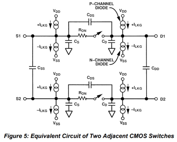
    The application note "Analog Switches and Multiplexers Basics" (MT088) from Analog Devices provides the following equivalent diagram of an analog switch (figure below, in application note it has the number 5). 

    Under the concept of capacity of an open analog switch, I understand the capacity shown in figure  under the name Cds.
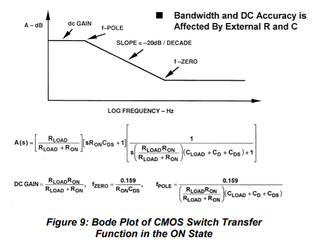
    The same document indirectly shows the algorithm for calculating this parameter (calculate using the f pole parameter(figure below, in application note it has the number 9) the Cds capacity). When calculating, I assumed that f pole = Bandwidth.

    Is it possible to calculate this parameter (Cds) using this algorithm, or is it necessary to use other algorithms for calculating this parameter for the analog switch? And if the calculation using such an algorithm is possible, is it possible to take into account the influence of temperature on this parameter?

    Thanks for the answer.
    Sincerely, Artem Panishev.

  • Hi Artem,

    Yes you can, but the on capacitance will most likely short well before the C_DS capacitor, so in general this can be assumed to be an open circuit within the operating parameters of the switch. And yes bandwidth is realistically the f_pole mark, it is just in general that this value is very small in typical operating conditions of the part that it doesn't affect it as much. Using this formula and typical bandwidth can give you an approximate solution, however there may be some inaccuracies due bandwidth for our devices being spec'd at a typical value only - so that value may fluctuate a bit more. 


    As for the temperature piece, the capacitances won't vary greatly with temperature, and the main concern is leakage currents and on resistance with respect to temperature, but we don't have a great system to integrate temperature into this because it typically isn't a significant contributing factor.

    However if you would like to include the capacitors between channels there is a  caveat and that is we don't directly spec C_SS, and this part wouldn't contain a C_DD (That looks closer to a 2 channel 1:1 device where this would be more apparent). We can get an approximation of this values by using the cross talk figure shown below:

    At f = 1MHz we are at -64dB (typ) of gain between the two channels, that means if the second pin is unconnected, or connected to a high impedance there will be a voltage gain of -64dB - which for a 1 volt signal would drop it down to ~631uV. If we assume there is a 1M Ohm load to ground we can find the current going through the capacitor, this is a decently accurate assumption because the cross talk voltage is measured with a volt meter.  If we just take voltage magnitude into consideration we have a voltage divider equation of 631uV = 1V * (1M Ohm)/ (1M Ohm + |Z_c|).  -> solving for |Z_c| :

    |Z_c| = 1M Ohm * V/ 631uV - 1 M Ohm ~ 1.584 G Ohms. |Z_c| = |1/sC| = R_c = 1/(2 * pi * 1MHz * C) -> C = 1 / (2 * pi * 1MHz * 1.584 G Ohms) = 100 aF (10^-18).

    There are a few assumptions baked in as well, assuming no resistance and only a capacitor between the two inputs, and cross talk will vary across frequency range so this value is also not constant, but can be worked out using the above process with the key harmonics in the system being taken account because they can see this capacitor differently depending on the frequency content.

    If you have any other questions please let me know, and I will see what I can do to help you!

    Best,

    Parker Dodson