This thread has been locked.

If you have a related question, please click the "Ask a related question" button in the top right corner. The newly created question will be automatically linked to this question.

TS3A27518E: can't access SD/eMMC card

Part Number: TS3A27518E
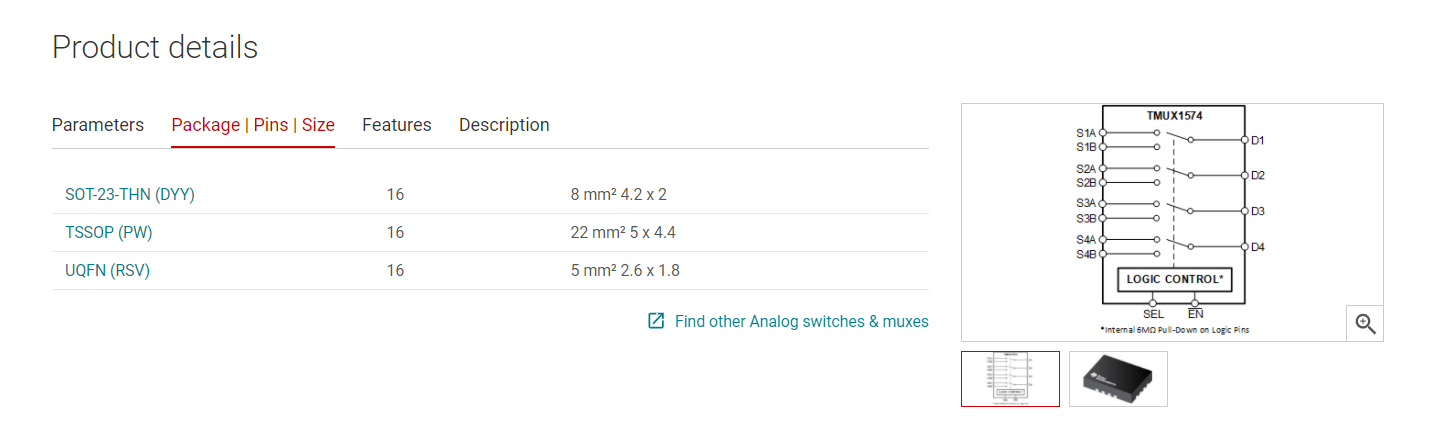
Other Parts Discussed in Thread: TMUX1574

Hi,

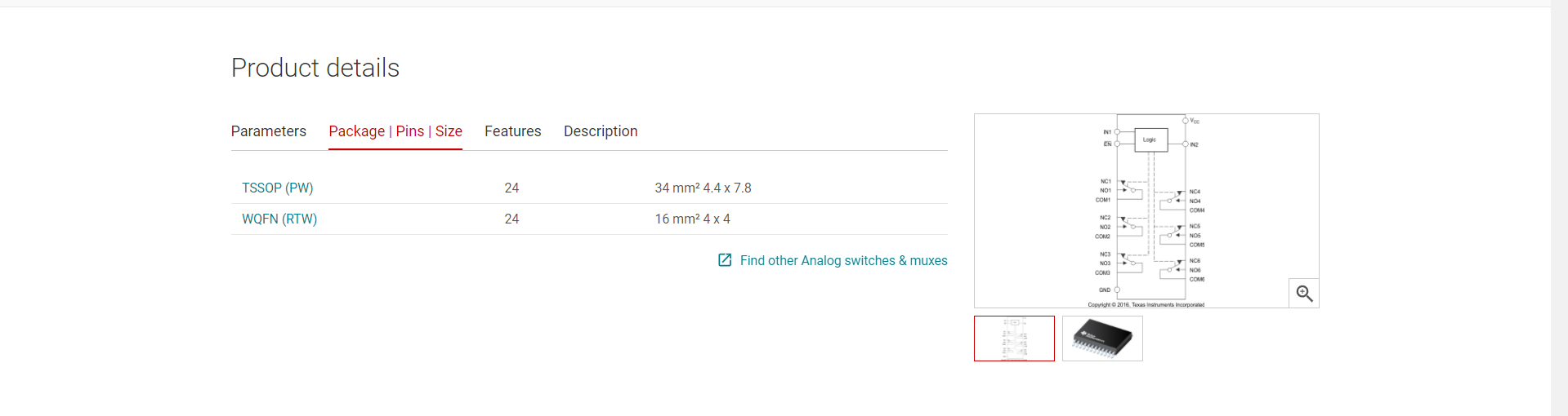
I'm using the TS3A27518E for switch MMC or SD card with SDIO bus from I.O. USB2244 (HW MassStorage for higher speeds) to MCU with SDIO. EN signal is wired to GND via 100K resistor. IN1 and IN2 are connected together, connected to MCU GPIO and pulled down to GND by 100K resistor. USB2244 is connected to NC signals and it works well. MCU is connected to NO signals and MCU has no access to SD card. So I decided to unsolder TS3A27518E and connect COM signals to NO via wires - and it works well (MCU has access to SD card, all works with no issue). Signal on IN1 and IN2 is correct (0 V or 3,3 V - as I set for switching... 0 V for COM-NC and 3,3 V for COM-NO).

Schematics, layout and wire modification for pass-through is attached.

Note: R603 in schema is not placed (DNP = Do Not Place)

files.zip

  • Hi Marvin,

    I don't see anything wrong with the schematic / layout.

    If possible is there a way to get scope shots of COM/NC/NO/IN1/IN2 during a switching cycle - if it is a problem with the mux sometimes the problem can be detected by seeing the waveforms during a cycle  of IN1/IN2 being 1 or 0. 

    Have you tested the suspect unit on a different board and have you tested a different unit on the board that was failing? Do you have multiple failures?

    Please let me know so that I can help dig into this problem!

    Best,

    Parker Dodson

  • Hi Parker,

    Thanks for checking the schema/layout.

    I tried two prototype boards. On one board I made the wire modification - and all works well without switch. I had a new one switch soldered (on board where was wire modification). I had the soldering checked under a microscope. Soldering looks good. But problem is back. I tried to connect N.C pin (24. pin) to GND - it has no effect. I tried to change pull-down resistor on Enable pin from 100K to 4K7 - it has no effect too.

    I found a few description of this problem in some forums (for example one here in e2e: https://e2e.ti.com/support/switches-multiplexers/f/388/t/765358?TS3A27518E-TS3A27518-interfacing-with-SD-card

    There must be some other kind of problem.

    It is strange that USB2244 works properly on NC contacts at about twice the frequency.

  • Hi Marvin,

    After digging through some old threads - I think it could be possibly too much bus capacitance - as there have been other issues where this part struggles to access SD cards due higher bus capacitance. 

    If possible - we do have a multi-chip solution that will help lower Capacitance - and I think that might be the root cause of the issue. 

    The TMUX1574 is a 4 channel 2:1 switch with low capacitance -> you won't be sacrificing performance, and you can possibly shrink footprint for this switch with two of these (size comparison below), and regardless of package type 1ku pricing will be lower for the 1574 (2 1574's is < than 2  TS3A27518E's). The Unused ports of the 2nd TMUX1574 can be terminated to help improved high speed performance with 50 Ohm resistors. 

    TS3A27518E Package Options and footprint size:

    TMUX1574 Package Options:

    I think this should solve the problem - as I do suspect bus capacitance to be the problem - as nothing with the schematic/layout looks wrong and the solution was removing the switch (i.e. extra capacitance). 

    Please let me know if this is a possible option - or if you have any other questions!

    Best,

    Parker Dodson

  • Hi Parker,

    I performed a basic test using GPIO outputs with low frequency and the signals was correct.

    I took a few scope shots with SDIO switched to USB2244 and to MCU. Both signals looks bad. It really looks like a bus capacity problem. But USB2244 is likely to be more sensitive to changes in voltage levels than MCU. I had a really problem to get the scopes. I had a serious problem taking scope shots. After connecting the probes, communication from USB2244 often did not work. The connected probe is another capacity.

    The MCU starts at a low frequency (which looks OK) and then switches to a higher frequency. There it tests 1-wire communication and there is already a problem. It doesn't even get on 4-wire communication. USB2244 runs straight to a higher frequency and establishes communication on a 4-wire.

    If I use 2x TMUX1574, will there not be a bigger difference in parameters between the switches? Which signals will be better separated? CLK and DAT together and DAT0-DAT3 together?

    Do you have an application notes for routing signals with low capacitance? Traces and isolation has 10 mil. But there are testpoints in the way. Lenght of traces from eMMC storage to switch is about 1,4 inch. In middle of distance are testpoints with same pinout as SD card (so I could have wired SD card at traces). Lenght of traces from switch to MCU is about 0,6 inch. Lenght of traces from switch to USB2244 is about 0,8 inch.

    Note: 1st channel (red) is CLK, 2nd channel (yellow) is CMD, 3rd channel (violet) is DAT0, 4th channel (green) is DAT1. In attachement is picture with SDIO traces.

    SDIO.zip

  • Hi Marvin,

    There may be a bigger difference between two switches - but this difference (unless running IC at max operating conditions) is most likely still going to be within specs listed in the datasheet.  This device is pretty consistent across its specs so I don't think you will run into many problems.

    That being said here's a bit of an overview of what you should be able to expect:

    The Capacitance, On Resistance, and On Resistance Mismatch are going to determine how much error there is between parts.

    1. Capacitance: The largest factor with Parasitic Capacitances is the input frequency:

    As Frequency of a signal goes up the ON Capacitance will decrease. This means that the RC time constant will be smaller for higher frequency signals. For Signals above 10MHz you would look at < 4pF and if you are above 30MHz you can look at <2pF. This will be pretty consistent across parts - so with all the input signals being the same frequency the capacity added by this part will be very low - you could expect some deviation but not much more than a pF at higher frequency signals. 

    2. On Resistance - This part has flat on resistance which allows it to maintain a pretty consistent on resistance across supply voltage. For a 3.3V supply the on resistance will look like this across temp:

    For the 3.3V supply at 25C (bottom graph - black line) There is a slight increase with input voltage (from 1.1 ohm to 1.4 ohms) 

    Even when operating at higher temperature the resistance doesn't change much or rapidly so it will pretty consistent for all channels. 

    3. On resistance Mismatch: The mismatch in on resistance between channels is what causes differences in  prop delay which can cause the data/clock to not follow each other correctly. However for this part we are looking at a typical value of 0.07 Ohms typical and 0.28 Ohms max with the max condition only existing in high temp applications. I should note that the TS3A27518E has a typical mismatch of 0.3 ohms and worst case of 0.8 Ohms - and it is unrealistic for the mismatch - even between two different TMUX1574's  - to be larger than what the TS3A27518E has - I will go a bit more into this for the next point.

    4. Interchannel Skew: This essentially skewing of signals due to differences in prop delay - mainly caused by channel mismatch.  This is going to depend on the package - but the rule of thumb is that the prop delay and skew will decrease with a smaller package.

    Y axis is in picoseconds. Skew is related to C_On, R_On, and R_On mismatch. For the QFN (RSV) package we are looking at ~5ps of skew typically - and even if there is some larger differences between 2 IC's this skew will still most likely be < than TS3A27518E because the channel mismatch is typically worse than the TMUX1574 worst case channel mismatch. I don't think the ps of skew will be enough to hinder the application - but with a lot lower bus capacitance you will see improved performance.

    That being said we have 3 app notes that may be of use to you:

    High Speed Interface Routing

    Improve Stability with Low Con Multiplexers

    High Speed Layout Guidelines for Signal Conditioners and USB Hubs

    Please let me know if you have any other concerns about the 1574 or any other general questions!

    Best,

    Parker Dodson

  • Hi Parker,

    Thank you for information. I was looking for alternatives, but the TMUX1574 will be most suitable if I don't want to use BGA packages. Resistance and capacitance combination is pretty well. The only disadvantage is the use of two components.

    I think I have all I need. So I will try some prototype modifications on PCB for testing, but it will probably be necessary to draw a new PCB and have it manufactured to test the analog switches.

    So thanks again. I'll let you know how it turned out, but it will take at least another month before everything is redesigned, ordered and produced.

  • Hi Marvin,

    Sounds good - if you run into any issues or have any other questions feel free to post another thread or if this one hasn't locked by then you can reply here as well. I handle a lot of the E2E threads for multiplexers so If you post in this forum again I will be able to find it and answer it!

    Best,

    Parker Dodson