e2e,
I'm considering the analog input signal of TMUX1308-Q1. If the input voltage is 60mV, can the output error be within 1mV? The supply voltage is 5V.
Thank you,
Adam
This thread has been locked.
If you have a related question, please click the "Ask a related question" button in the top right corner. The newly created question will be automatically linked to this question.
e2e,
I'm considering the analog input signal of TMUX1308-Q1. If the input voltage is 60mV, can the output error be within 1mV? The supply voltage is 5V.
Thank you,
Adam
Hi Adam,
It depends on a few factors - namely loading conditions (insertion loss error), source impedance (error from leakage current), signal frequency (attenuation due to bandwidth).
The output is going to be Vout = Vin - I_sw * R_on . So the current through the switch is going to cause a voltage drop across the on resistance.
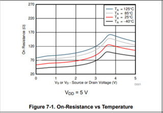
For the TMUX1308-Q1 at a 5V supply the following on resistance curve is present:

At a 60mV input you will have about a ~50 to 60 Ohm on resistance at room temperature. For less than 1mV of insertion loss that would require the load to request no more than ~16.67uA however the max rated resistance of this part is going to be up to 270 Ohms. At 270 ohms there could only be up to 3.7uA of current through the switch.
So for low error due to insertion loss the load impedance >= Max_ron * 59 in your application.
However there is also error due to on leakage currents - this is where the source impedance comes into play. To find error it is simply Verror = Id(on) * (Ron + Rsource). Ion(d) for this device is going to be, worst case, +/-800nA. which with the current information - Verror = (800nA) * (270 + Rs) = 216uV + 800nA * Rs. So depending on the value of Rs the error from leakage will also cause degradation. Verify the source impedance to calculate worst case error.
Finally signal frequency. In the first point we treat the mux as a resistor and the load as a resistor to get basic insertion loss value. However that is assuming DC current and while gives a good estimation for lower frequency applications - higher frequencies will change the impedance of the output capacitance as well as any capacitance on the load So there could be more loss for higher frequency signals - but this depends on the load as well.
So in short when the channel is actively channeling a signal through it, the error can be small - but the system operating conditions need to be taken into consideration.
1. Load Impedance >= Max Ron Expected * (Vin - Ver)/ Ver -> Load impedance >= 270 * (60mV - 1mV)/1mV -> 15.93k but the higher the load impedance the lower the insertion loss for the system will be.
2. Source Impedance - Higher Source Impedances will have higher errors due to leakage current -> keeping application cool if possible will help lower this error.
3. The Higher the signal frequency is the more attenuation there will be due to the parasitic capacitances.
If you have any other questions please let me know!
Best,
Parker Dodson
.