This thread has been locked.

If you have a related question, please click the "Ask a related question" button in the top right corner. The newly created question will be automatically linked to this question.

TS3A227E: Manual switch configuration problems

Part Number: TS3A227E

Hello,

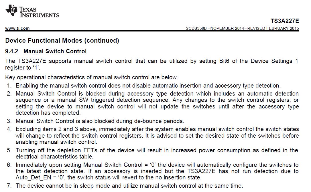
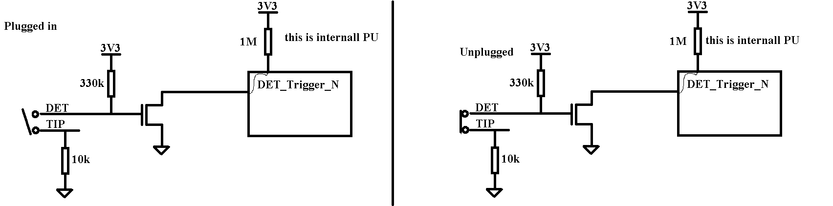
I am using the TS3A227E on my board.  The 4-pole headset I am using is only ever detected as a 3-pole headset.  I found an error in my schematic where I am missing a transistor and pull-up on the DET_TRIGGER_N line.  This means the polarity of the insertion event is wrong.

Regardless, I figured I could manually adjust the switches over I2C.

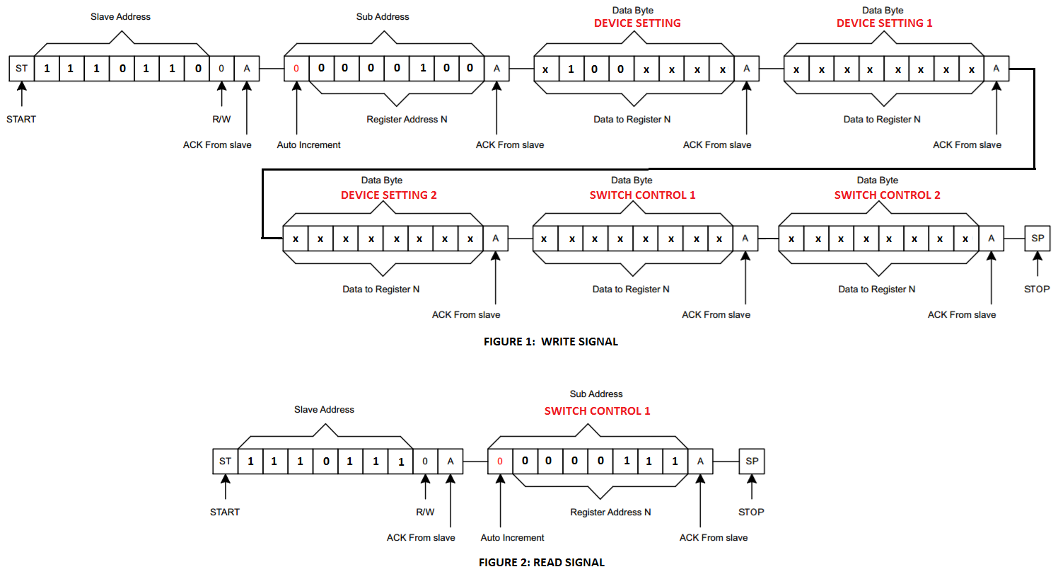
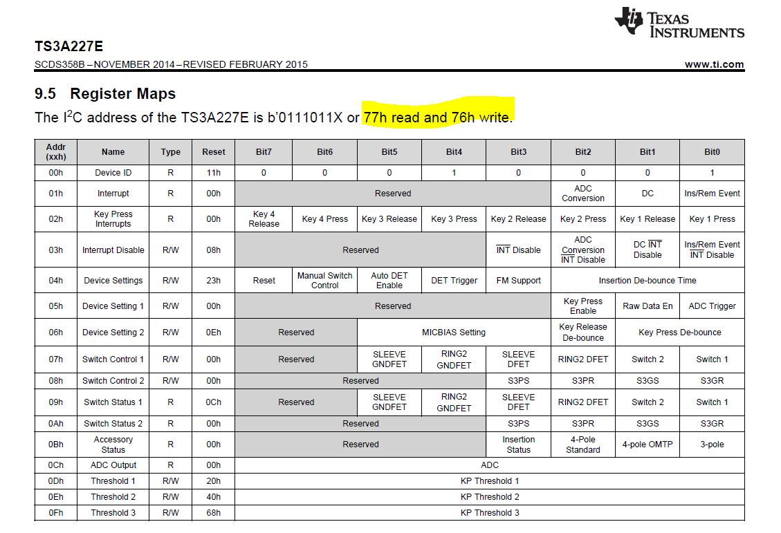
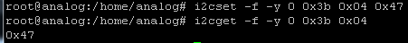
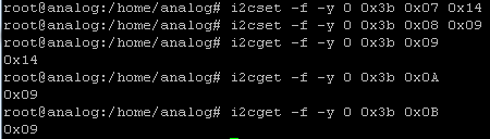
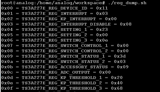
Typing  'i2cset -f -y 0 0x3b 0x04 0x07' allowed me to configure the 'Manual Switch Control Register'.

I tried 'i2cset -f -y 0 0x3b 0x09 0x14' to configure the 'switch control 1' register, but I cannot read back the changes I am writing to the part.

Am I missing a step in the process?

Cheers

Neil

  • Hello Neil,

    I think you may be using the wrong hex values.  Figure 1 below illustrates how you can write to the device setting registers and the switch control registers.  The x values should be a 1 or 0 in accordance to how you would like to set the register values.  Figure 2 shows how you would read the contents of register switch control 1.

  • Neil,

    To operate the device manually you need to follow the procedure beginning on page 21 of the datasheet.

    I noticed that you didn't start your commands by addressing the TS3A227E slave with its address 77xh or 76xh.

    This may be you issue.  Here is an appnote Understanding the I2C bus to help supplement I2C communication information in the TS3A227E datasheet.

    Thank you,

    Adam

  • I understand why you think the hex values are wrong.  The datasheet shows 0x77 and 0x76 as read and write.  I think this has to do with 7bit vs 8 bit word and how the data is being read.  Ill talk to the software lads and sort it out.

    Having said that, I can write to register 0x04 using the command I listed in my original post.  I can read back the register to see the contents are changing.

    I do not follow the description 9.4.2.

    I think my problem stemming from item 9.4.2.2 

    'Any changes to the switch control registers, or setting the device to manual switch control will not update the switches until after the accessory type detection has completed.'

    The 'Det_trigger_n' in my schematic has the wrong polarity.  It is missing the transistor and pull-up recommended in your EVM ( http://www.ti.com/lit/ug/slvuad9/slvuad9.pdf

  • I have been trying to configure the device for a 4-pole standard headset.
    I can read the contents from register 0x00 (Device ID Register).
    i2cget -f -y 0 0x3b 0x00
    Read back is 0x11

    Now I read the contents from register 0x04 (Device Settings Field Register).
    i2cget -f -y 0 0x3b 0x04
    Read back is 0x23

     
    I want to manually change register 0x04 (Device Settings Field Register). 
    I set bit 6 to a '1' to enable manual switch control.
    I set bit 5 to a '0' to disable the auto detection.
    i2cset -f -y 0 0x3b 0x04 0x47
     
    I verify the register contents.
    i2cget -f -y 0 0x3b 0x04
    Read back is 0x47.

     
    Now, I want to configure the switch settings for registers 0x07 and 0x08 so I can utilize a standard 4 pole configuration.  I copied the information from table 18, Switch Status.
     
    Reserved                             0                              Reserved                              0
    Reserved                             0                              Reserved                              0
    SLEEVE GNDFET               0                              Reserved                              0
    RING2 GNDDFET               1                              Reserved                               0
    SLEEVE DFET                    0                              S3PS                                     1
    RING2 DFET                       1                              S3PR                                     0
    S1                                        0                              S3GS                                     0
    S2                                        0                              S3GR                                     1
     
    I want to write register 0x07 (Switch Control 1 Field Descriptions) with '0001 0100' = 0x14. 
    i2cset -f -y 0 0x3b 0x07 0x14
    I want to write register 0x08 (Switch Control 1 Field Descriptions) with '0000 1001' = 0x09. 
    i2cset -f -y 0 0x3b 0x08 0x09 
    Now to verify the switch changes I want to read registers 0x09 and 0x0A.
    i2cget -f -y 0 0x3b 0x09
                    Read back is 0x14
    i2cget -f -y 0 0x3b 0x0A
                    Read back is 0x09
    Register 0x0B (Detection Results Field Descriptions) tells us what microphone is detected.
    i2cget -f -y 0 0x3b 0x0B
                                    Read back is 0x09
                                                    

    This indicates a 3 pole accessory is detected.  Upon manually configuring the registers, I expected it to show me a 4-pole headset was connected.  So why didn’t it? 
    I 'detected' different from what I manually configure the IC for?  Should I disregard what I read from register 0x0B because it is technically not 'detecting' anymore?
    Cheers
    Neil

    CONFIGURING FOR A FOUR POLE STANDARD
     
     
    I can read the contents from register 0x00 (Device ID Register).
    i2cget -f -y 0 0x3b 0x00
    Read back is 0x11
    Now I read the contents from register 0x04 (Device Settings Field Register).
    i2cget -f -y 0 0x3b 0x04
    Read back is 0x23
     
    I want to manually change register 0x04 (Device Settings Field Register).  So I set bit 6 to a '1' and bit 5 to a '0'. 
    i2cset -f -y 0 0x3b 0x04 0x47
     
    I verify the register contents.
    i2cget -f -y 0 0x3b 0x04
    Read back is 0x47.
     
    Now, to configure the switch settings for registers 0x07 and 0x08 so I can utilize a standard 4 pole configuration.
     
    Reserved                             0                              Reserved                             0
    Reserved                             0                              Reserved                             0
    SLEEVE GNDFET                                0                              Reserved                             0
    RING2 GNDDFET              1                              Reserved                             0
    SLEEVE DFET                       0                              S3PS                                      1
    RING2 DFET                        1                              S3PR                                      0
    S1                                           0                              S3GS                                      0
    S2                                           0                              S3GR                                     1
     
    I want to write register 0x07 (Switch Control 1 Field Descriptions) with '0001 0100' = 0x14. 
    i2cset -f -y 0 0x3b 0x07 0x14
    I want to write register 0x08 (Switch Control 1 Field Descriptions) with '0000 1001' = 0x09. 
    i2cset -f -y 0 0x3b 0x08 0x09


    Now to verify the switch changes I want to read registers 0x09 and 0x0A.
    i2cget -f -y 0 0x3b 0x09
                    Read back is 0x14
    i2cget -f -y 0 0x3b 0x0A
                    Read back is 0x09
    Register 0x0B (Detection Results Field Descriptions) tells us what microphone is detected.
    i2cget -f -y 0 0x3b 0x0B
                                    Read back is 0x09
                                                   
    This indicates a 3 pole accessory is detected.  Upon manually configuring the registers, I expected it to show me a 4-pole headset was connected.  So why didn’t it? 
  • Neil,

    The register Accessory Status 0Bxh is only linked to the automatic accessory detection sequence and will only tell you what type of accessory it detected during its sequence. It will not check the status of the switches you manually controlled. If you would like to confirm the switch status and what type of configuration the internal switches are at a given point in time you need to read 09xh and 0Axh registers switch status 1 and switch status 2.

    Thank you,
    Adam
  • Hi Adam,

    I was able to solve the 'DET_TRIGGER_N' circuit problem.  The tip voltage is being driven to VDD/2 = 1.65V by our audio codec.  So transistor Q1 never shuts off because VGS(th) is 1V to 2.5V.

    The circuit does not correctly identify the 4 pole accessory.  It reads it as a 3-pole accessory.

    I also am unable to get anything out of the microphone input, by recording a file and playing it back through the codec.

    Cheers

    Neil

  • Neil,

    What type of accessory are you attempting to plug in?  Could you be running into one of these issues?  There are app notes that help explain in more detail how the audio jack switches work within these postings. 

    Thank you,

    Adam

  • Hi Adam,

    I read through the two links you posted, I am using a 4-pole standard pair of earbuds.

    The Audio codec, ADAU1761, drives the tip to VDD/2 (1.65V).  

    When the headset is plugged in, DET_TRIGGER_N and TIP are not connected, DET_TRIGGER_N is pulled up to 3.3V which turns on the transistor.  

    When the headset is unplugged, DET_TRIGGER_N and TIP are connected, DET_TRIGGER_N is driven to 1.65V which is not enough to turn off the transistor (VGS_TH is 1.0 V to 2.5V) .  Have you run into something like this before?  Would a comparator work better than a transistor?

    Also, I don't have the GND_SENSE line connected to codec ground, could this be an influence?

    Cheers

    Neil

  • Neil,

    You will need to satisfy the Vih and Vil level of the DET_TRIGGER pin getting the high to low transition upon insertion to initiate the detection sequence. 


    I have not come across this issue because typically I see the audio jack operate opposite the way yours does. When the device is inserted it connects the two contacts in the jack which can easily pull the DET_trigger pin low.

    With the 330k and 10k voltage divider the voltage on your gate will be ~0.1V and the source is grounded.  The Vgs = ~0.1 V which is <your Vgs_th of 1V and the FET should be turning off. 

    The Ground sense shouldn't have any impact on initiating the detection sequence.   

    Adam

  • Hi Adam,

    That doesn't make any sense because I am using the same audio connector as the TS3A227E-EVM (SJ-43515TS-SMT-TR).

    While the TS3A227E-EVM doesn't have the audio codec included, I confirmed it behaves the same as my crude drawings indicate.

    The trigger detect won't work because the codec drives TIP to a specific voltage. Is this typical of what a customer runs into? Do the audio codecs drive a voltage onto the TIP?

    Do you have examples of a codec being used with the the TS3A227E I could look at and compare?

    Cheers
    Neil
  • Neil,

    Unfortunately, we do not have a reference design with this device interfacing with a codec.  I do not have much knowledge with codecs and the drive on the tip pin.  Maybe you could AC couple the signal path to remove the bias?  You may want to trying the audio codec e2e forum to see if they have any thoughts about what types of outputs codecs supply.  

    Adam

  • Hi Adam,

    The entire design is hinged on the tip voltage at this point in time. Do you know of any TI audio codecs off hand I could look at as an example? If not I will go and have a peak and also write in the codec forum.

    Cheers
    Neil
  • I'm sorry Neil I do not know any audio codecs off the top of my head. I would recommended posting to the audio codec forum.