This thread has been locked.

If you have a related question, please click the "Ask a related question" button in the top right corner. The newly created question will be automatically linked to this question.

TS3V713EL: 10 to 1 port VGA MUX

Part Number: TS3V713EL
Other Parts Discussed in Thread: TS3V330, TS3V340, TS3V712E, TS3V712EL

I need to take 10 VGA sources (ports) and multiplex down to 1 output monitor display.

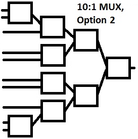
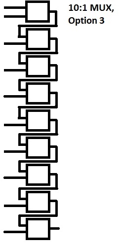
The TS3V713EL says it can be used as a 2:1 mux. Do I take 9 of these devices to implement the 10 to 1 mux? Any other recommendations? Thank you.

  • Hi Roland,

    Using 9 TS3V713EL is a feasible solution. It could be more helpful if you can share couple of thoughts.

    1. Do you need to level shift the VGA signals between the transmitter and receiver?

    2. What is the max bandwidth required for your VGA channels.

    3. How many signals are consisted of your VGA interface? We have seen customers using 3-wire VGA, 4-wire VGA, 5-wire VGA and 7-wire VGA.

    4. Is I2C also required in your case?


    Beside TS3V713EL, we also offer the following video muxtiplexers.

    TS3V330
    TS3V340
    TS3V712E
    TS3V712EL
  • Fan,

    Thank you for the reply.

    My 10 DP video sources will each utilize the NXP PTN3392BS 2-lane DisplayPort to VGA adapter IC.

    I believe I do not need any extra level shifting.

    Worst case display resolution of 1920 x 1200, 60 Hz yields bandwidth of ~210MHz. 

    I require 7-wire VGA: R, G, B, HSYNC, VSYNC,SDA, and SCL.

    My 10 sources are spaced over approx 9", my pcb will be approx 9.5" x 1"(?). Does it matter how I arrange the 9 2:1 switches? 

    Do I limit the # of chips I cascade together, for instance Options 1 and 2 cascade max of 4 chips, but Option 3 cascades 9 chips

    Thank you, Roland

  • Hi Roland,

    Our vidoe mux supports up to 1.36GHz bandwidth, but the -3dB point drops quickly as the number of cascaded stage increases.

    For 4-stage video mux, the -3dB point will fall at 160MHz. In other words, your assessment is correct. Your design will be limited by the number of chips cascaded together.
  • Fan,

    I get a different total system bandwidth for 4 stages, I calculated 650MHz. Unless I calculated incorrectly. 

    How did you calculate a bandwidth of 160MHz for 4 stages?

    I used 

    but only for 4 stages, not for 6 stages shown above.

    9 stages calculated to 433MHz.

    Thank you, Roland

  • Hi Roland,

    I re-caculated and your result is more right than my previous one. Sorry about that. My new -3dB frequency for 4 stage MUX is 591MHz.


    One system setup not quite clear to me is the loading at your receiver side. I assume it is 50 Ohms. If you have 50 Ohm loading present at the output of the last stage of MUX, not only does the sufficiant bandwidth matter, but the attenuation is also an important factor for some customers we have helped. You may want to check if it matters to your system.


    For example, if the Ron is roughly 5 Ohms of each MUX. When we cascade 4 stage MUX, the Ron is 20 Ohms in total. If the loading is 50 Ohms, there will be 28% signal attentuation even at low frequency. In addition, the 50Ohm transmitter side also needs more signal integrity attention, since more signal will reflect back due to the 20 Ohm impedance mismatch.


    Overall, I do not think cascading 4 stage TS3V713EL is a feasible solution to your requirement. Or, you may have different opinions.
  • Fan,
    I expect a 75 ohm double termination: R, G, and B each have a 75 ohm termination to GND, a 75 ohm VGA cable, and another 75 ohm termination inside the RGB monitor. The Ron of the cascaded stages would present a big mismatch/attenuation. How did you arrive at 28% attenuation?
    Do you have an alternative method to switch the VGA signals? What about PNP transistors?
    Roland
  • Fan,

    What do you think if we use the TI TS2DDR2811, a 1GHz Bandwidth 8-bit SPST switch?

    They would be arranged as a 1 stage cascade, 1 chip for each of my VGA ports. The R signals are all connected together at the output, similar for the G, B, etc. Only would enable 1 chip at a time corresponding to the port that is selected. The other chips are in Hi-Z.

    Roland

  • Hi Roland,

    If board layout area is not a concern, I would use 10 TS2DDR2811 for your 10:1 7-wire VGA application. It is much easier to achieve high bandwidth as well as better channel-to-channel isolation performance. Again, the cost is layout area.

    Since I am not quite familiar with your system, the Coff and off isolatino are the parameters I would look into before adopt this 10 8-bit SPST solution. One VGA channel is conducting while the other 9 channels are turned off, the total capacitive loading at the B port is

    Con + 9xCoff = 8pF + 9x2.5pF = 30.5pF. And isolation is -40dB at 200MHz.


    If you are not quite satifised with either the loading cap or isolation performance, we may consider using five TS3V712E at the 1st stage and then add five TS2DDR2811 as the 2nd stage. The isolation performance will be much better since there are two stages. And the cap loading at the output of the 2nd stage will be reduced to:

    Con + 5xCoff = 8pF + 5x2.5pF = 20.5pF.