This thread has been locked.

If you have a related question, please click the "Ask a related question" button in the top right corner. The newly created question will be automatically linked to this question.

TS5A22364: Asking for the TS5A22364 schematic review

Part Number: TS5A22364

Hi Team,
Could you help review TS5A22364 schematic?
Customer uses this part to do the audio switch.
However, the output waveform is distortioned.

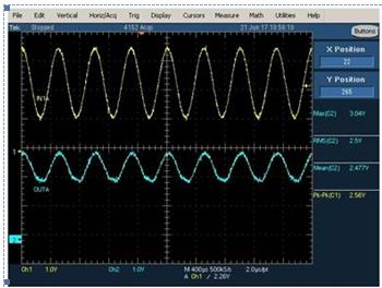
yellow line is input signal. blue line is the output waveform. the blue waveform is distortion and only half amplitude of input signals.

Customer removed R308/R309. Use 4.7uF to replace 220uF on C251 and C250. 

The waveform is till not good. Please provide your comment for this. Is that ok to add AC de-coupling cap before and after the audio switch?


Thanks,
SHH

  • Hello SHH,

    One very important parameter that contributes to distortion is ron(flat), which indicates that ron varies with input voltage.  Higher supply voltages minimize this (figure 1).  Could you tell us what the customer's supply voltage is to their TS5A22364?

  • Hi Patrick,
    The VCC is 3.3V. Is that enough for this application?


    Thanks,
    SHH
  • SHH,

    3.3V should be sufficient for this particular case.  

    Can you provide a little more about the surrounding circuitry including the source and load?  The more we know the better we are able to understand your problem.   If you do not feel comfortable providing this information, we can take it offline and discuss through email.

    When you say that "this part is to do an audio switch," would it be reasonable to presume that either output load is an 8 ohm speaker?  Since this is an audio application, we presume that signals passed will be at or below 200KHz. So each of those coupling capacitors should at most provide 0.1693Ω of impedance.  You may want to consider larger caps as they have a lower impedance. 

    As for the signals you provided, where did you take them?  If the measured signals were from between the device and the AC coupling capacitors, I would expect the signals to be centered around zero.  What pull-up resistors are used to set the output DC bias the client has in their signal?

    Has the customer noticed similar behavior if they tried replacing the TS5A22364 switch with a short or a wire?

  • Hi Patrick,

    What is the NO and NC input voltage range? 0~3.3V? or -3.3 to 3.3V?

    Thansk,

    SHH

  • Hello SHH,

    According to the recommended operating range in the datasheet shown in Table 1 below, the acceptable NO and NC input voltage range for this particular case would be -2.2 to 3.3V.

    Table 1