A related question is a question created from another question. When the related question is created, it will be automatically linked to the original question.
If you have a related question, please click the "Ask a related question" button in the top right corner. The newly created question will be automatically linked to this question.
TS3A227E: Can I use this device without the i2c operation or pins?
Thank you for your kind support. Let me ask you one more thing.
I got a question from the customer about how to pin assign when not using I2C (stand-alone). Could you give me your advice?
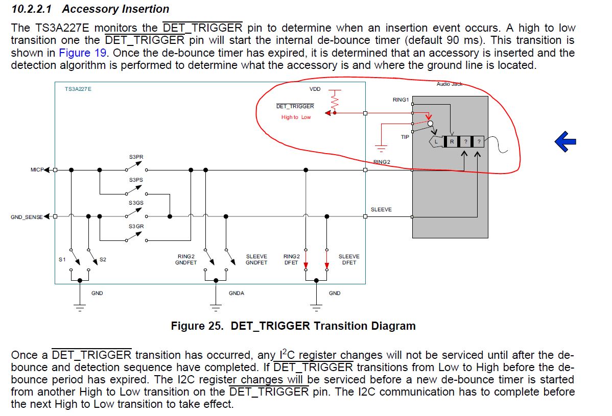
1.Could you tell me how to handle the DET_TRIGGER pin in stand-alone. Is it OK with OPEN processing?
2.Could you tell me how to handle the MIC_PRESENT pin in stand-alone. Is it OK with OPEN processing?
3.The default setting is SW selection automatic selection. When using the default setting, Is it correct by understanding that SW control is unnecessary?
1.Could you tell me how to handle the DET_TRIGGER pin in stand-alone. Is it OK with OPEN processing?
The DET_TRIGGER pin needs to see a high to low transition on the pin to initiate the detection algorithm that determines what type of headset is plugged into the system.
This high to low transition can be accomplished using a GPIO from a process or you can use the physical mechanical switch in the audio jack connector with the internal pull up in the TS3A227E DET_TRIGGER pin to create this transition on the pin when a head set is inserted into the jack.
2.Could you tell me how to handle the MIC_PRESENT pin in stand-alone. Is it OK with OPEN processing?
The MIC_PRESENT pin is used to tell the system that there is a microphone plugged in. This is an open drain output and can be pulled up to VDD when it is unused.
3.The default setting is SW selection automatic selection. When using the default setting, Is it correct by understanding that SW control is unnecessary?
The switch registers default to the reset values. You can see that manual control of the internal switch matrix is disabled by default.
The audio jack you show does not contain a switch that can be used to trigger a detection sequence. You will need to select on that has a switch like shown in the TS3A227E EVM if you want to make use the insertion of an audio accessory triggering the TS3A227E detection sequence.
You can see that pin 5 of the audio jack is connected from pin 2 until something is inserted into the plug and then it will move out of the way and break the connection between pin 5 and pin 2.
If you would like to use your jack above you will need to supply the TS3A227E DET_TRIGGER pin a high to low transition or use I2C commands to trigger the detection sequence to configure the TS3A227E switch matrix to the appropriate accessory.
How does the IC know when to run the detection sequence? You need to tell all TI audio jack detection switches when to run the detection. You can see this same need in all datasheets including the TS3A226AE datasheet.
Once you tell the IC to run the detection everything else is automatic. The IC saves system power by only running the detection sequence when it is told and is idle the rest of the time.
You can create a rising or falling edge in your system in many different ways including:
1) Using a GPIO from a microprocessor
2) Using a pull up or pull down circuit with the audio jack's that include a mechanical switch. You can see examples of this circuit in the datasheets and in the EVMs (Unfortunately the jack you showed a as shown above doesn't have the mechanical switch needed to make this circuit)
3) Using I2C commands for the TS3A225E or TS3A227E devices (not possible with TS3A226AE)