Part Number: TMDSEMU110-U
Other Parts Discussed in Thread: CC1310,
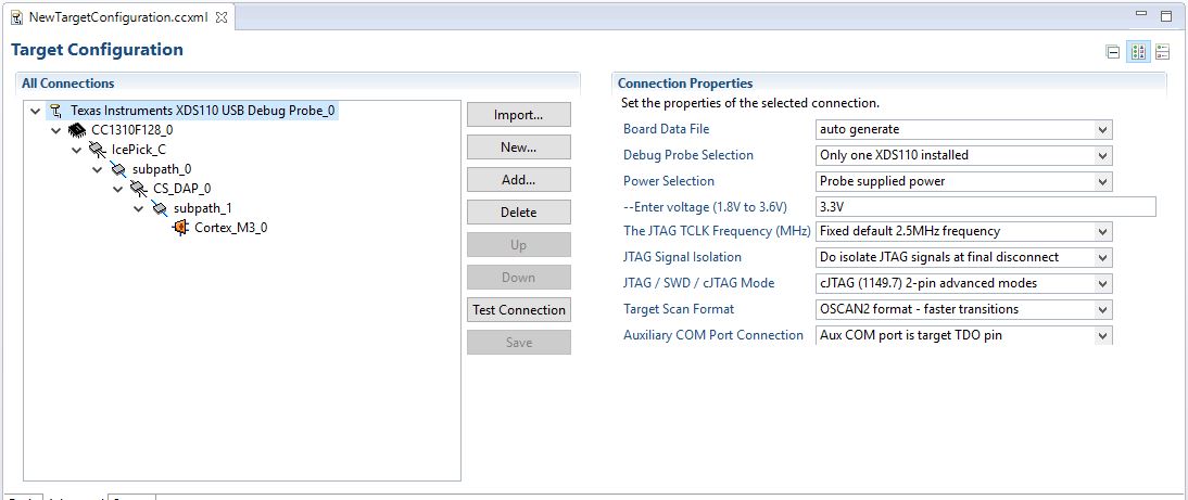
Tool/software: Code Composer Studio
Hi,
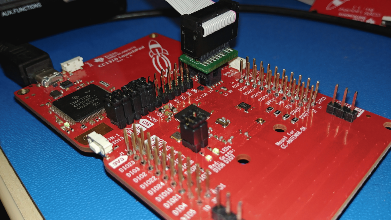
I just bought a new TMDSEMU110-U to program CC1310 based custom board. I used a cTI 20 pin to ARM 10 pin adapter along with TMDSEMU110-U JTAG programmer. I tried both CCS and Flash Programmer 2. However, in both the cases CC1310 IC is not detecting. Also, note that custom board is working fine. I am able to program the same board through XDS110 on CC1310 launchpad. Posting the Error below when I verify the connection in CCS. Any suggestion would be greatly appreciated.
[Start]
Execute the command:
%ccs_base%/common/uscif/dbgjtag -f %boarddatafile% -rv -o -S integrity
[Result]
-----[Print the board config pathname(s)]------------------------------------
C:\Users\apurv\AppData\Local\TEXASI~1\CCS\
ti\0\0\BrdDat\testBoard.dat
-----[Print the reset-command software log-file]-----------------------------
This utility has selected a 100- or 510-class product.
This utility will load the adapter 'jioxds110.dll'.
The library build date was 'Jul 21 2017'.
The library build time was '19:36:41'.
The library package version is '7.0.48.0'.
The library component version is '35.35.0.0'.
The controller does not use a programmable FPGA.
An error occurred while hard opening the controller.
-----[An error has occurred and this utility has aborted]--------------------
This error is generated by TI's USCIF driver or utilities.
The value is '-267' (0xfffffef5).
The title is 'SC_ERR_XDS110_TARGET_SUPPLY'.
The explanation is:
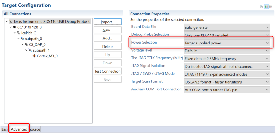
The controller could not detect valid target supply. Check target
JTAG connection and/or connection setting specifying voltage level.
[End]