This thread has been locked.

If you have a related question, please click the "Ask a related question" button in the top right corner. The newly created question will be automatically linked to this question.

CCS/UCD3138HSFBEVM-029: XDS200 with UCD3138HSFBEVM-029.

Part Number: UCD3138HSFBEVM-029
Other Parts Discussed in Thread: UCD3138, UCD3138A

Tool/software: Code Composer Studio

Hi, 

I try to use a XDS200 with UCD3138HSFBEVM-029.

But, I cannot connect UCD3138HSFBEVM-029.

What kind of causes?Please teach me.

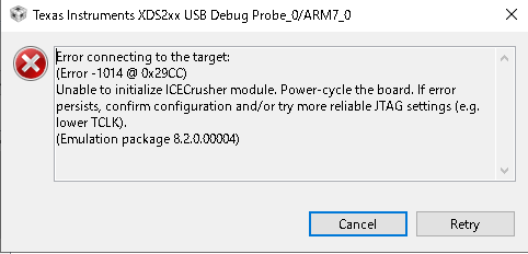
1:click a debug button. Then, I get a dialog 

Error connecting to the target:
(Error -1014 @ 0x29CC)
Unable to initialize ICECrusher module. Power-cycle the board. If error persists, confirm configuration and/or try more reliable JTAG settings (e.g. lower TCLK).
(Emulation package 8.2.0.00004)

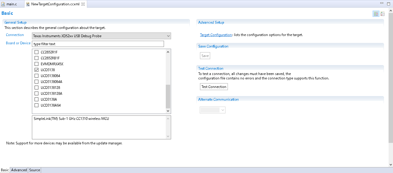
2:make a NewTargetConfigulation.ccml, and I do a test. Then I get a result

[Start: Texas Instruments XDS2xx USB Debug Probe_0]

Execute the command:

%ccs_base%/common/uscif/dbgjtag -f %boarddatafile% -rv -o -S integrity

[Result]


-----[Print the board config pathname(s)]------------------------------------

C:\Users\username\AppData\Local\TEXASI~1\
CCS\ccs910\0\0\BrdDat\testBoard.dat

-----[Print the reset-command software log-file]-----------------------------

This utility has selected a 560/2xx-class product.
This utility will load the program 'xds2xxu.out'.
The library build date was 'Jun 3 2019'.
The library build time was '14:44:57'.
The library package version is '8.2.0.00004'.
The library component version is '35.35.0.0'.
The controller does not use a programmable FPGA.
The controller has a version number of '13' (0x0000000d).
The controller has an insertion length of '0' (0x00000000).
This utility will attempt to reset the controller.
This utility has successfully reset the controller.

-----[Print the reset-command hardware log-file]-----------------------------

This emulator does not create a reset log-file.

-----[An error has occurred and this utility has aborted]--------------------

This error is generated by TI's USCIF driver or utilities.

The value is '-233' (0xffffff17).
The title is 'SC_ERR_PATH_BROKEN'.

The explanation is:
The JTAG IR and DR scan-paths cannot circulate bits, they may be broken.
An attempt to scan the JTAG scan-path has failed.
The target's JTAG scan-path appears to be broken
with a stuck-at-ones or stuck-at-zero fault.

[End: Texas Instruments XDS2xx USB Debug Probe_0]

Best Regards,

Yuji.

  • Even though XDS-200 is not supported and verified for debugging UCD3138, the following steps may help to stablish JTAG connection:

    Before attempting to connect through JTAG:

    1) Be aware that the ROM in the current version of UCD3138(32K version) sets the value of the

    Bitfield MiscAnalogRegs.IOMUX.bit.JTAG_CLK_MUX_SEL == 2; , in other words when in ROM mode, JTAG is disabled as default.

    In order to enable JTAG, set the value of the above bit-field to zero through the PMBus "Device GUI"’s Memory Debugger.

    The revised device UCD3138A will have JTAG enabled by default when operating in ROM mode.

    2) Make sure that in the downloaded firmware JTAG related IOMUX bits are set to zero.

    MiscAnalogRegs.IOMUX.bit.JTAG_CLK_MUX_SEL == 0;

    MiscAnalogRegs.IOMUX.bit.JTAG_DATA_MUX_SEL == 0;

    3) Make sure that none of the JTAG pins are assigned as GPIOS using the Global IO settings:

    MiscAnalogRegs.GLBIOEN.bit.TCK_IO_EN = 0;

    MiscAnalogRegs.GLBIOEN.bit.TDI_IO_EN = 0;

    MiscAnalogRegs.GLBIOEN.bit.TDO_IO_EN = 0;

    MiscAnalogRegs.GLBIOEN.bit.TMS_IO_EN = 0;

    Both 2) and 3) statements may be placed in the init_gpio() function that is typically located in gpio.c file.

    Hope this helps.

    Regards,

  • Thanks for your response.

    I have a more question.

    Could you please teach me.

    1) How can I set ROM mode bit with "Device GUI" ?

    I connected evaluation board by USB interface Adapter . But, Memory Debugger is disable.

    2),3) I will try it, when I resolved the above question.

    4) I decided a development tool that introduced by this page's

    http://www.tij.co.jp/product/jp/UCD3138/toolssoftware

    In this page show XDS-200. But, XDS-200 is unsupported UCD3138 ?

    I want to know what tool is recommended for JTAG connection with UCD3138 ?

    Regards,

  • In order to be able to go back to ROM, the command 0xD9 (rom BACK DOOR) needs to be implemented and fully functional.

    Which firmware are you using?

    Based on the amount of NACKs in your screen shot, I guess that this firmware does not have the support needed.

    The best way to have all the memory debugger and ROM back door support is to download the firmware for one of TI's EVMs and then modify it for your needs.

    For your information, the memory debugger (in the Device GUI) can be a pretty good replacement for JTAG for debugging of UCD3138.

    So, you may not even need a JTAG probe.

    But if you decide to use JTAG, XDS110 or XDS100v2 are the recommended ones for UCD3138.

  • Thanks for responses my many questions.

    1)
    >Which firmware are you using?

    I use a UCD3138HSFBEVM-029 and
    firmware is default written in UCD3138HSFBEVM-029.
    connector PC with board is USB-to-GPIO made by TI ( within evm kit )
    (www.digikey.com/.../4288762)

    2)
    > Based on the amount of NACKs in your screen shot, I guess that this firmware does not have the support needed.

    I will try to write firmware.
    firmware's extension is ".x0", right?

    3)

    > But if you decide to use JTAG, XDS110 or XDS100v2 are the recommended ones for UCD3138.

    I see, I will buy XDS110.

    And, what is recommended tools for Device GUI ? 

    USB-to-GPIO is OK ?

    4)

    I clicked "Memory Debugger" then I required password.

    Device GUI need some license ? 

    Could you please teach me , how to get a password.

    Regards,

  • I tried proposed solution in response Aug 26, 2019 2:16 AM.

    I could connect XDS200 with UCD3138HSFBEVM-029 board.

    thank you for your advice.

    But, I have a some problem.

    when I do a build a "HSFB_Firmware-1.1"

    I got this result. 

    What kind of causes ?

    **** Build of configuration UCD3138 for project UCD3138HSFBEVM_029 ****

    "C:\\ti\\ccs910\\ccs\\utils\\bin\\gmake" -k all

    (rm device_id.obj) & (perl ../../build_scripts/create_date_dot_h_CCS5.pl)
    makefile:207: recipe for target 'pre-build' failed
    'rm' は、内部コマンドまたは外部コマンド、
    操作可能なプログラムまたはバッチ ファイルとして認識されていません。
    Can't open perl script "../../build_scripts/create_date_dot_h_CCS5.pl": No such file or directory

    makefile:211: recipe for target 'post-build' failed
    Can't open perl script "../../build_scripts/checkmem_CCS5.pl": No such file or directory
    Can't open perl script "../../build_scripts/build_CCS5.pl": No such file or directory
    gmake[2]: [post-build] Error 2 (ignored)

    **** Build Finished ****

    And then I try debug with above build result and XDS200. then I get message.

    Regards,

  • The error messages:

    perl script "../../build_scripts/checkmem_CCS5.pl": No such file or directory
    Can't open perl script "../../build_scripts/build_CCS5.pl

    can be remove by going to your project properties, -> under CCS Build -> Steps Tab -> Post Build Steps:

    Remove the Perl script part an just stay with:

    "${CG_TOOL_HEX}.exe" -x "${BuildArtifactFileName}" -o "${BuildArtifactFileBaseName}.x0" -memwidth 8

    Please also make sure that you follow the CCS configuration in the attached document.

    This should help, but if you are still having issues, then replace XDS200 with XDS110. As XDS200 is not fully tested with UCD3138.

    Regards,

    css-one-click-download-debug.pdf

  • If the above addresses your question, please set the status of this post to resolved.

    Regards,

  • Thanks a response.

    and Sorry, I have a more question.

    I got a below popup and console message, when I try to debug with XDS200. 

    I think it like a this problem ( https://e2e.ti.com/support/tools/ccs/f/81/p/808065/2990499 )

    What kind of causes ? this factor is the above build error ? or debugger ?

    ARM7_0: GEL Output: /nMemory Map Initialization Complete/nARM7_0: GEL Output: /tMemory Map Setup for Flash at Address 0x0ARM7_0: Device ID validation option selected.
    ARM7_0: File name: C:\ti\DigitalPower\HSFBFirmware-1.1\UCD3138-HSFB\HSFB_Firmware-1.1\UCD3138_HSFB_VM\UCD3138\UCD3138HSFBEVM_029_UCD3138.out
    ARM7_0: Device ID validation cannot be done of files of type: out
    ARM7_0: Device ID validation FAILED.
    ARM7_0: Remapping PFlash to 0x00000000, DFlash to 0x00018800
    ARM7_0: File Loader: Memory write failed: Unknown error
    ARM7_0: GEL: File: C:\ti\DigitalPower\HSFBFirmware-1.1\UCD3138-HSFB\HSFB_Firmware-1.1\UCD3138_HSFB_VM\UCD3138\UCD3138HSFBEVM_029_UCD3138.out: Load failed.
    ARM7_0: Unable to terminate memory download: NULL buffer pointer at 0x320

    Regards, 

  • Have you followed all the instructions in the attachment that I have posted for you?

    css-one-click-download-debug.pdf

  • Thanks for your response.

    I set up according to the PDF you presented.

    I still got a below message.

    ARM7_0: File name: C:\ti\DigitalPower\HSFBFirmware-1.1_orig\UCD3138-HSFB\HSFB_Firmware-1.1\UCD3138_HSFB_VM\UCD3138\UCD3138HSFBEVM_029_UCD3138.out
    ARM7_0: Device ID validation cannot be done of files of type: out
    ARM7_0: Device ID validation FAILED.
    ARM7_0: Remapping PFlash to 0x00000000, DFlash to 0x00018800
    ARM7_0: Boot ROM Region at memory range 0x0000A000 - 0x00001000
    ARM7_0: Data RAM Region at memory range 0x00019000 - 0x00001000
    ARM7_0: Flash Region #0 at memory range 0x00000000 - 0x00008000, erase page 0x400 bytes
    ARM7_0: Flash Region #1 at memory range 0x00018800 - 0x00000800, erase page 0x20 bytes
    ARM7_0: Writing Flash @ Address 0x00000020 of Length 0x000057e8
    ARM7_0: File Loader: Memory write failed: Unknown error
    ARM7_0: GEL: File: C:\ti\DigitalPower\HSFBFirmware-1.1_orig\UCD3138-HSFB\HSFB_Firmware-1.1\UCD3138_HSFB_VM\UCD3138\UCD3138HSFBEVM_029_UCD3138.out: Load failed.
    ARM7_0: Unable to terminate memory download: NULL buffer pointer at 0x320

    And , I unchecked "Validate against Device ID in hex based firmware file" (like a below picture)

    then I get a below message.

    ARM7_0: GEL Output: /nMemory Map Initialization Complete/nARM7_0: GEL Output: /tMemory Map Setup for Flash at Address 0x0ARM7_0: Device Identification (DEV) 0x347F, Device is UCD3138
    ARM7_0: Boot ROM Region at memory range 0x0000A000 - 0x00001000
    ARM7_0: Data RAM Region at memory range 0x00019000 - 0x00001000
    ARM7_0: Flash Region #0 at memory range 0x00000000 - 0x00008000, erase page 0x400 bytes
    ARM7_0: Flash Region #1 at memory range 0x00018800 - 0x00000800, erase page 0x20 bytes
    ARM7_0: Device ID validation option not selected.
    ARM7_0: Remapping PFlash to 0x00000000, DFlash to 0x00018800
    ARM7_0: Boot ROM Region at memory range 0x0000A000 - 0x00001000
    ARM7_0: Data RAM Region at memory range 0x00019000 - 0x00001000
    ARM7_0: Flash Region #0 at memory range 0x00000000 - 0x00008000, erase page 0x400 bytes
    ARM7_0: Flash Region #1 at memory range 0x00018800 - 0x00000800, erase page 0x20 bytes
    ARM7_0: Writing Flash @ Address 0x00000020 of Length 0x000057e8
    ARM7_0: Performing Erase on memory range: 0x00000000 - 0x00008000
    ARM7_0: Performing Flash Program on memory range: 0x00000020 - 0x00005808
    ARM7_0: Writing Flash @ Address 0x00005810 of Length 0x00000466
    ARM7_0: Performing Flash Program on memory range: 0x00005810 - 0x00005C76
    ARM7_0: Writing Flash @ Address 0x00005c80 of Length 0x00000028
    ARM7_0: Performing Flash Program on memory range: 0x00005C80 - 0x00005CA8
    ARM7_0: Writing Flash @ Address 0x00007f58 of Length 0x0000001f
    ARM7_0: Performing Flash Program on memory range: 0x00007F58 - 0x00007F77
    ARM7_0: Writing Flash @ Address 0x00000000 of Length 0x00000020
    ARM7_0: Performing Flash Program on memory range: 0x00000000 - 0x00000020
    ARM7_0: Writing Flash @ Address 0x00018800 of Length 0x00000170
    ARM7_0: Performing Flash Program on memory range: 0x00018800 - 0x00018970
    ARM7_0: File Loader: Memory write failed: Unknown error
    ARM7_0: GEL: File: C:\ti\DigitalPower\HSFBFirmware-1.1_orig\UCD3138-HSFB\HSFB_Firmware-1.1\UCD3138_HSFB_VM\UCD3138\UCD3138HSFBEVM_029_UCD3138.out: Load failed.
    ARM7_0: Performing checksum based verification on memory range: 0x00000000 - 0x00008000
    ARM7_0: Checksum of memory range 0x00000000 - 0x00007FFC is 0x0044BB93
    ARM7_0: Writing checksum for memory range 0x00000000 - 0x00008000 to 0x00007FFC, value 0x0044BB93
    ARM7_0: Performing checksum based verification on memory range: 0x00018800 - 0x00019000
    ARM7_0: Checksum of memory range 0x00018800 - 0x00019000 is 0x0006C0E8
    ARM7_0: Flash Programmer: Checksum verification failed for range 0x00018800 - 0x00019000; expected 0x0006C10F, actual 0x0006C0E8


    I found a thread ( https://e2e.ti.com/support/processors/f/791/t/625958 )

    A solution In this thread is to use a specific version CCS.

    UCD3138 need a specific version CCS?  ( Now, I use Code Composer Studio Version: 9.1.0.00010 )

    Regards, 

  • Use of the specific version of CCS does not matter as much.

    But the compiler version recommended for UCD3138 is TI v5.2.9 :

    You can install this version of compiler through Help -> Install new software menu.

    Regards,

  • Thanks for response.

    This project already set a below picture.

    This project use TI v5.2.4. 

    I ordered XDS110 . When I get it, I will try again .

    Regards,

  • I have a problem.

    I use Device GUI with USB-To-GPIO.

    I make a program and try to write UCD3138. then I got a below picture.

    and yesterday, I success to write UCD3138HSFBEVM-029 sample program.

    after I got this message, I cannot connect to UCD3138.

    How I write firmware again. Please help me.

    Regards,

  • Can you check after this happens if you are in ROM mode?

    I am guessing that something either resets when in Flash, or gets hanged up in interrupt.

    This way PMBus can not communicate any more.

    Do you have a statement similar to the one below?

    if(GioRegs.FAULTIN.bit.FLT3_IN == 0)// Re-Check pin assignment (ADC_EXT/SYNC may be?)

    {

    // clear_integrity_word();

    }

    if so, make sure clear_integrity_word(); is commented out.

    And also make sure that at the end of ISRs you clear the interrupt flag.

    Otherwise, you are going to be stuck inside the ISR and PMBus handler which is getting called from main() will not have the chance to communicate.

    Regards,

  • Thanks response.

    I added some process in fast interrupt. I thought it disturb to PMBus. Added source written in end of message. 

    I want to try a clear flash or download firmware. So I want to know a below.

    1) How to change to ROM mode ? I can it in CCS ?

    and I click Scan Device in ROM ...

    then I got error.

    2)In main.c, clear_integrity_word(); is commented out. It's right ?

        volatile unsigned int dummy;
        if(GioRegs.FAULTIN.bit.FLT3_IN == 0)// Re-Check pin assignment (ADC_EXT/SYNC may be?)
        {
    //      clear_integrity_word();
        }

    3) Can I write flash by SWD to UCD3138 ? Now, I cannot connect JTAG( with XDS200 ) and PMBus( with USB-To-UART)


    Regards,

    ==========Added source in FIQ==================

    int16 testvalue = 0;
    #pragma INTERRUPT(fast_interrupt,FIQ)
    void fast_interrupt(void)
    {
    if(testtest == 0){
    MiscAnalogRegs.GLBIOVAL.all |= MASK_LED1;
    testtest = 1;
    }else{
    MiscAnalogRegs.GLBIOVAL.all &= ~MASK_LED1;
    testtest = 0;
    }
    if(supply_state == STATE_STABLE){
    testvalue = FeCtrl0Regs.EADCVALUE.bit.ABS_VALUE;
    testvalue = 1000;

    //Dpwm0Regs.DPWMPRD.bit.PRD = 2500; //o nly puts in PRD bit field = 40000/16 2500 *4ns=10us period
    Dpwm0Regs.DPWMEV1.bit.EVENT1 = 100; //EV1 is the only low resolution event register
    Dpwm0Regs.DPWMEV2.bit.EVENT2 = 1250; //both forms are the same nly puts in PRD bit field = 40000/16 2500 *4ns=10us period
    Dpwm0Regs.DPWMEV3.bit.EVENT3 = testvalue; //EV1 is the only low resolution event register
    Dpwm0Regs.DPWMEV4.bit.EVENT4 = testvalue + 1250; //both forms are the same

    }


    if(cpcc_on)
    {
    vloop_filter = (signed int) (Filter0Regs.FILTERYNREAD.bit.YN);
    iloop_filter = (signed int) (Filter1Regs.FILTERYNREAD.bit.YN);


    if (iloop_filter > vloop_filter)
    {
    if( cc_flag ==1)
    {

    Filter0Regs.FILTERCTRL.bit.KI_STALL =0;
    if (abs(v_input_error) < 10)
    {
    cc_flag = 0;
    Filter0Regs.FILTERCTRL.bit.OUTPUT_MULT_SEL =2;
    }
    }


    LoopMuxRegs.DPWMMUX.bit.DPWM0_FILTER_SEL =0; //
    LoopMuxRegs.DPWMMUX.bit.DPWM1_FILTER_SEL =0; //
    }


    else if (iloop_filter < (vloop_filter - 0x200))
    {
    LoopMuxRegs.DPWMMUX.bit.DPWM0_FILTER_SEL =1; //
    LoopMuxRegs.DPWMMUX.bit.DPWM1_FILTER_SEL =1; //
    cc_flag =1;
    Filter0Regs.FILTERCTRL.bit.KI_STALL =1;
    Filter0Regs.FILTERCTRL.bit.OUTPUT_MULT_SEL =0;

    }

    }

    Dpwm2Regs.DPWMINT.bit.PRD_INT_EN = 1; //clear interrupt flag

    }

    ===========================