


Tool/software: Code Composer Studio
Dear Sir,
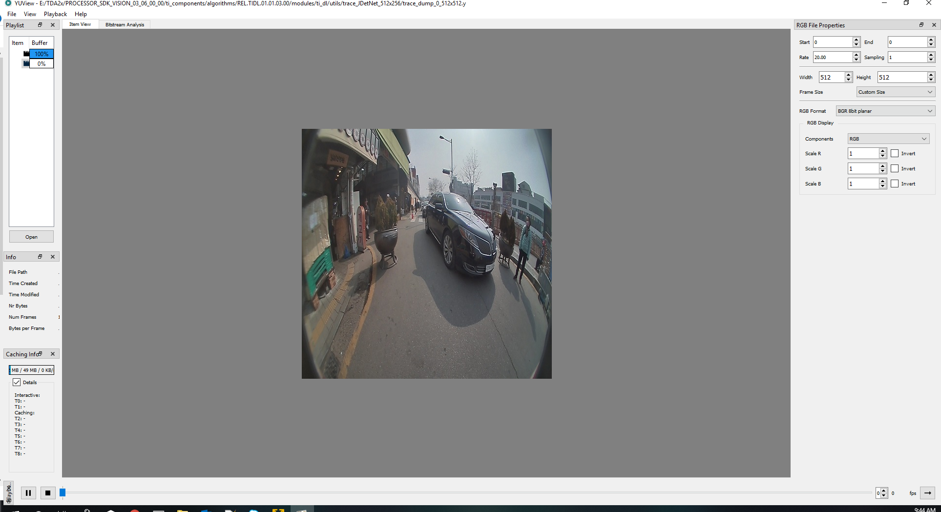
Observation: For TDA2x:
Resolution is 512x512x3
Layer dump: 0(Data layer)trace_dump_0_512x512.zip
Size: 512x512x3 = 786432 bytes
Layer 0 visualized through YUView is below:
Observation: For TDA4x:
Resolution is 512x512x3
Layer dump: 0(Data layer)caffe_tidl_infer_msi_mobilenet_pd.txt_0000_00003_00512x00512.zip
Size: 512x512x3 (x2)extra is observed = 1572864 bytes
Layer 0 visualized through YUView is below:
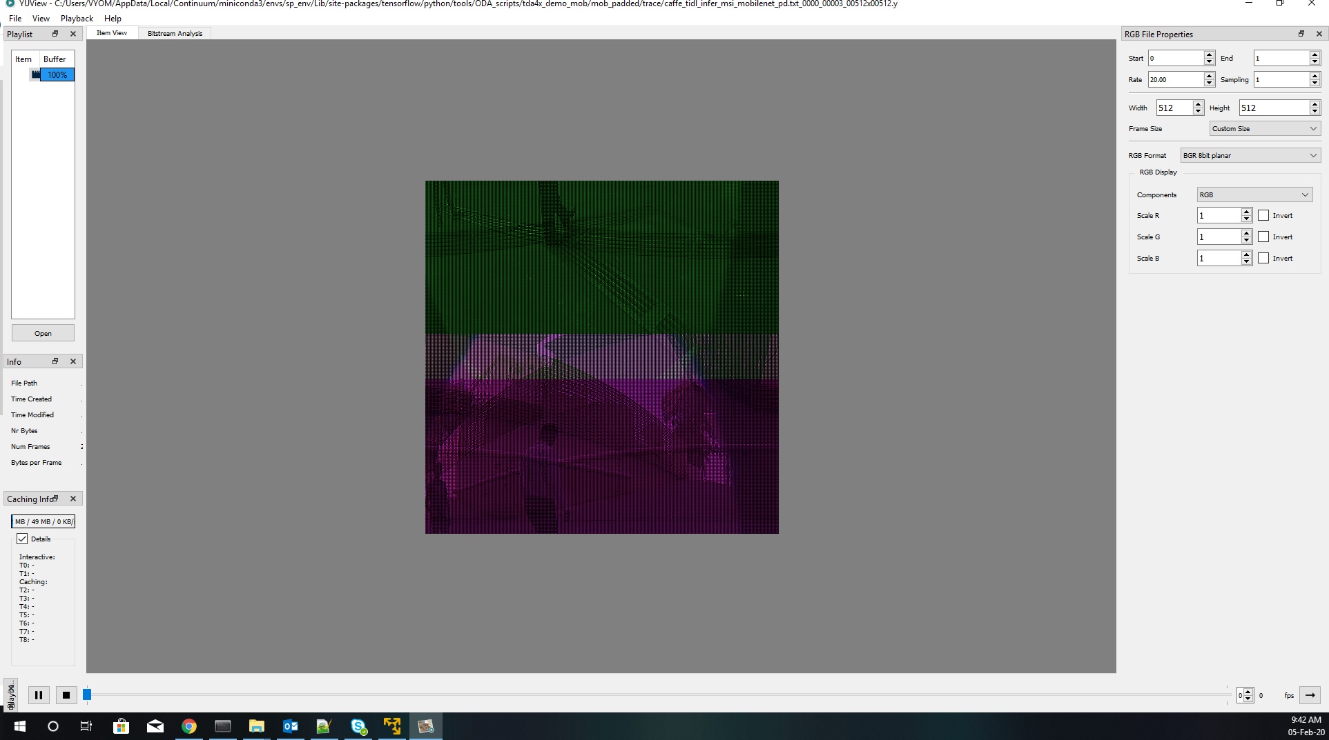
For TDA4x:
Why the layer dumps has the double size of the input(512x512x3)?
How to confirm that input to the model is correct?
Kindly do the needful.
Thanks and Regards,
Vyom Mishra


