This thread has been locked.

If you have a related question, please click the "Ask a related question" button in the top right corner. The newly created question will be automatically linked to this question.

CCS/EK-TM4C123GXL: EK- TM4C123GXL

Part Number: EK-TM4C123GXL

Tool/software: Code Composer Studio

Hi Everyine,


I need to develop a control of an AC-DC converter using the Tiva C. For that, I studied the ADC module and started thinking about some experiments. I tried to get samples from your own PWM source and changed the sampling frequency to check the graph on the CCS, but it didn't work, I couldn't see a PWM signal, even at small PWM frequencies.

Is this really possible?

Thank you!

  • Hello,

    I can't comment much about the specifics of the device or device peripherals, but I am curious regarding your comment:

    JOAO OLIMPIO CALIMAN said:
    changed the sampling frequency to check the graph on the CCS, but it didn't work, I couldn't see a PWM signal, even at small PWM frequencies.

    I am assuming you are using the time/frequency graph. Can you explain in more detail what "didn't work"? Was the graph simply blank? A screenshot of the graph and graph properties would be helpful.

    Thanks

    ki

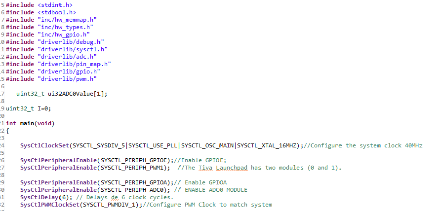
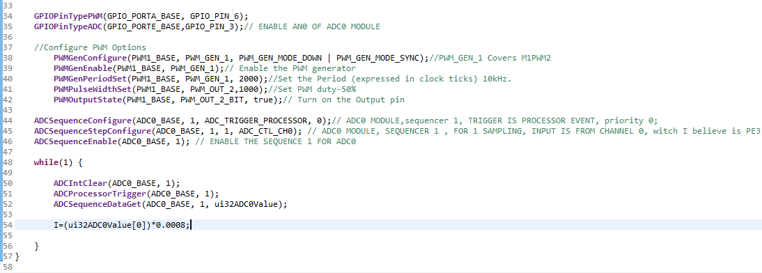
  • The images are:

    -The code;

    -The Conection;

    -The "Measures"

  • Hi,

      You wrote:

    ADCSequenceStepConfigure(ADC0_BASE, 1, 1, ADC_CTL_CH0); // Assigning ADC_CTL_CH0 to step 1 of sequencer 1 of ADC0

     I will suggest you do:

    ADCSequenceStepConfigure(ADC0_BASE, 1, 1, ADC_CTL_CH0 | ADC_CTL_END); // Assigning ADC_CTL_CH0 (PE3) to step 0 of sequencer 1 of ADC0 and step 0 is the last step of the sequencer.