This thread has been locked.

If you have a related question, please click the "Ask a related question" button in the top right corner. The newly created question will be automatically linked to this question.

CCS/CC2652R: Trouble Halting Target CPU: (Error -2064 @ 0x0), Error: (Error -1170 @ 0x0) Unable to access the DAP

Part Number: CC2652R
Other Parts Discussed in Thread: SYSCONFIG

Tool/software: Code Composer Studio

Hi,

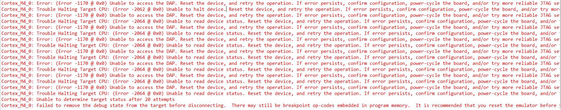
I have the following problem. One specific programm always stops with the error message shown below. I already removed all breakpoints. I realised, when flashing another programm the problem does not appear.

The programm was build on the Project Zero example integrating the sensor controller using the Time-to-digital converter, and sending the data via bluetooth.

What might be the mistake here? Are there any solutions for that?

Thanks a lot.

  • Hi,

    This error is usually caused by a disconnect between the Debug Probe and the device on the target board and some troubleshooting tips are shown in the Debugging JTAG page below:

    https://software-dl.ti.com/ccs/esd/documents/ccs_debugging_jtag_connectivity_issues.html 

    If you have a UART communications happening at the same time, there is an outstanding bug (EXT_EP-9768) that is related to this scenario - check its status in the link SIR in my signature below. 

    Hope this helps,

    Rafael

  • Hi,

    thanks for your replay. I have an UART communication, so that this might be the problem. I followed your link, but I couldn't find the outstanding bug.

    Could you post the direkt link to the bug?

    Thanks a lot.

  • Hi,

    Sorry, I put the wrong bug code. I fixed that above.

    Regards,

    Rafael

  • Hi,

    now I can't see the SIR link any more underneath your signature. It disappeared.

  • Hi,

    Interesting; the link shows for me at my signature. 

    At any rate, the direct link is:

    https://sir.ext.ti.com/jira/browse/EXT_EP-9768 

    Regards,

    Rafael

  • Hi,

    I found out that the problem was the integration of the Sensor Controller Code into Code Composer Studio.

    I used the HWI to read out the sensor controller memory and this brought me to the mentioned problem.

    Now I changed to a SWI for the integration of the Sensor controller. This works fine right now. But a further problem appeared.

    I am using a SWI for a periodic clock as well which sends my data via Bluetooth. I figured out, that without sending my data everything is working, but if I switch in the clock, my programm shows againt the error as before. I think there must be a priority problem. How can I change the priority for one of those Interrupts? Is ther another way to send data out at a specific time point or with a specific frequency?

    I think the highes priority is to copy all data form the AUX RAM to the main RAM, sending it just has to happen some time before the next copy action.

    I hope that there is any solution for it.

    Thanks

  • Hi,

    Thank you for reporting back the results of your findings; over the course of our investigation both the developer and us found out it was heavily tied to the running application, which could be easily throwing the device off. This matches with your observation.  

    At any rate, since the new issue you are seeing involves other parts of the software, I will inform the device experts as they are more knowledgeable about their software than I. 

    Regards,

    Rafael 

  • HI VV,

    Could you share/elaborate on your use of SWI for SC and as clock? What exact modules are you using in terms of software and how do you use them? 

    Is there any other components in the application that could be good to know about, like do you have a watchdog enabled or similar?

  • Hi,

    my project is based on the Project Zero example of simplelink_cc13x2_26x2_sdk_3_40_00_02.

    For the integration of the SC in CCS I followed the instruction in:

    http://software-dl.ti.com/lprf/simplelink_academy/modules/sc_01_project_from_scratch/sc_01_project_from_scratch.html#bonus-tasks-1-ndash-integrate-with-ble

    The programm is very simple, advertising, getting data from sensor controller and send it.

    I did some more long term tests over night. I noticed that when I am sending data whithout having SC integrated the system doesn't break.

    The integration of the sensor controller shows the error even if I am not sending any data. It takes between a few minutes up to a few hours until it stops running.

    My sensor controller samples with a frequency of 1 khz and uses 2 buffers which are exchanges when data is transfered to the main CPU. Each buffer has the size of 800 values. So it interrupts the CCS programm approx. every 0.8s.

    The main programm sends advertisments every 200ms.

    I am not using a whatchdog. I can't think of anything else I changed. I just wrote my costum profile.

    Here is my code relevant for the integration of the sensor controller

    static void ProjectZero_init(void)
    {
       
            // Initialize the SCIF operating system abstraction layer
            scifOsalInit();
            scifOsalRegisterCtrlReadyCallback(scCtrlReadyCallback);
            scifOsalRegisterTaskAlertCallback(scTaskAlertCallback);
    
            // Initialize the SCIF driver
            scifInit(&scifDriverSetup);
    
            // Set the Sensor Controller task tick interval
            uint32_t N = 1000;  // 1kHz RTC --> Not sure about it!
            // Enable RTC ticks, with N Hz tick interval
            scifStartRtcTicksNow(0x00010000 / N);
    
            // Start the "ReadCap" Sensor Controller task: Sensor Controller starts to measure
            scifStartTasksNbl(1 << SCIF_READ_CAP_TASK_ID);
    }
    
    
      // SCIF driver callback: Task control interface ready (non-blocking task control operation completed)
    static void scCtrlReadyCallback(void)
    {
        // Notify application `Control READY` is active
        ProjectZero_enqueueMsg(APP_MSG_SC_CTRL_READY, NULL);
    } // scCtrlReadyCallback
    
    static void scTaskAlertCallback(void)
    {
        // Notify application `Task ALERT` is active
        ProjectZero_enqueueMsg(APP_MSG_SC_TASK_ALERT, NULL);
    } // scTaskAlertCallback
    
    static void processTaskAlert(void)
    {
        // Clear the ALERT interrupt source
        scifClearAlertIntSource();
    
        //... Access Sensor Controller task data structures here ... for whole array
        // For each available output buffer ...
        while (scifGetTaskIoStructAvailCount(SCIF_READ_CAP_TASK_ID,
                                             SCIF_STRUCT_OUTPUT) > 0)
        {
            SCIF_READ_CAP_OUTPUT_T* pOutput = scifGetTaskStruct(
            SCIF_READ_CAP_TASK_ID, SCIF_STRUCT_OUTPUT);
    
            for (int n = 0; n < SCIF_READ_CAP_BUFFER_SIZE; n++)
            {
                DATA_ARRAY[n] = pOutput->tdcBuffer[n];
                
            }
    
            //Hand the buffer back to the Sensor Controller
            scifHandoffTaskStruct(SCIF_READ_CAP_TASK_ID, SCIF_STRUCT_OUTPUT); 
        }
    
        // Acknowledge the ALERT event
        scifAckAlertEvents();
    } // processTaskAlert


    I hope that it helps. Let me know about any thing else you need.

    Thanks a lot.

  • Hi VV,

    The code as given above seems OK to me, I do not see any obvious errors. Would it be possible to share the failing project in question so that I can run it myself?

  • Hi M-W,

    it would be possible to share the project with you if it is handled more privately. How can this be done?

  • Hi VV,

    You could send me the project privately in a PM if you do not want to share it here in the open. 

  • Hi VV,

    Just giving you and update that I'm currently looking into your example code.

  • Hi VV,

    Still working on finding the root cause of the issue. In short, what is happening is that you are getting a VDDR brown out which causes the device to reset. The question I'm trying to figure out now is why you are getting it. It does not seem to be connected to either SC or BLE but this particular combination of the two.

  • Thank you for your update.

    I highly appreciated that you put so much effort into it. :)

  • Hi,

    do you have any updates?

  • I'm sorry to say I don't. I'm trying to isolate the reason step by step but as of now I'm having a hard time finding the exact combination causing it. Due to not having access the lab equipment (as I'm restricted to working from home) I also have some delays in performing the tests I would want to do in order to try to catch exactly what happens when this problem occurs. 

    I'm however still running variations of it on my desk to evaluate different combinations.

  • Hi,

    Sorry for asking again. Have you made any progress?

    Time is running and I need to finish the project. If you could not find what is wrong, is there any possibility how I can make it run?  I think the task is quiet simple and there must be a way to do it.

    The MCU is made for using the Sensor Controller and Bluetooth, so there must be a solution. Is there any example using the MCU with both of them?

    Thanks a lot.

  • No worries, I understand you are waiting for feedback.

    My "desk" test have not really yielded any further results than what we already know. The reset happens in some scenarios and it seems to be related to a VDDR brown out. I just recently (today actually) got access to a remote setup for me to to do some HW measurements together with the SW to see if this could enlighten us a bit more.

    What you are doing should not really be an issue, the only error I could actually find in your project was that you set the SC project to work in Low-Power mode which is not supported when using the TDC etc. I did move this to active on my side by this did not seem to be the root cause of your issue.

    I should have some feedback in a day or two on how my HW measurements went.

  • Hi VV,

    A quick update, I've worked on getting some remote testing going but I'm having an issue with the LP on the other side and have not been able to produce any good results yet. I'm however still working on this.

  • Hi VV,

    Update, got the setup running remotely and while I could re-create the issue while running on debugger power, it seems to not be as frequent with external power supply as I have not seen a crash for over 24h. I did however ran into a forced IT security update on my lab computer so I had to restart the test again...

    Hopefully it will be left alone for the weekend to give a good idea of how it works with the external power supply.

  • Hi,

    how did the the test go?

    Does it work with the external power supply?

  • Hi VV,

    Concluded my latest test run this weekend and the results is split. It seems to have to do with the power supply on the board in question and not the code. The short story is that I can only see the issue when the debugger is connected AND power is sourced from the same board. As soon as power is sourced from another board (disconnecting the 3v3 jumper and connecting in 3v3 to the chip from another LP/power source this seems to be a non issue. 

    As of now, I'm trying to figure out why this might be but if you could try out doing the same that would be great.

  • Thanks a lot.

    Does it run if you disconnect the debugger and  use the power supply from the board? That did not work for me neither.

    I will try your test version  at the end of this week.

  • Hi VV,

    If I start the application and disconnect the debugger it seems to also run fine (it has for the last 24H at least). I have however noticed that the application is dependent on the BIM to start from a cold boot (I guess it is based on Project Zero?).

  • Hi,

    yes it is based on project Zero.

    It is true, that the problem does not appear with the debugger disconnected, but the bluetooth data stop to be sent. So I think the same problem appears, but we don't see it, as the debugger is disconnectd.

    Have you tried to implement another example project with bluetooth and the sensor controller? That would be an option to try. I tried it with the simple_peripheral project, but same result when I integrate the sensor controller.

    If ther was any example with both element integrated running normally, I could put my data into that code.

    I am a bit supriesed that I am the first person who has this problem, as the sensor controller is made for exactly these two things, transfering data from the sensor controller via bluetooth to a laptop. Don't you have any example running?

  • Hi VV,

    I will try give you another project you could base it on as soon as I got time to put one together. The issue itself is very odd and you are the only one I have ever seen having this issue, in all my cases the device continued to work (advertising on BLE etc) for the full period of the test, I did never see it stop running (except when having power + debugger on the same board). 

    There is plenty of projects and users of this combination and you are the first a I know about having an error like this. As said before, the use-case is valid, there is something funky going on in this case.

  • Hi VV,

    Here is a small Simple Peripherla + Sensor Controller example (running as one would expect). You could try to put your things into this step by step and see how it turns out and let me know.sp_scs.zip

  • Hi M-W,

    I found out what was causing the error. The sensorcontroller uses the Time-to-digital converter measuring the time with 96MHz based on the  RCOSC clock. This clock is also used for the TI-RTOS and therfore, the programm crashed. When useing the XOSC clock, everything works fine.

    In the technical reference manuel part 19.4.5.1 it is mentioned that both are using the same clock.

    https://www.ti.com/lit/ug/swcu185d/swcu185d.pdf?ts=1593422444776&ref_url=https%253A%252F%252Fwww.ti.com%252Fproduct%252FCC2652R

    It would have been very helpfull if this was also mentioned in the sensor controller studio manuel .

    Thanks a lot for all you have done for me. :)

  • Hi VV,

    Strange, there should be no problem to use RCOSC on both sides if that is what you are saying you see? It could be something else related to the RCOSC in that case of the XOSC works for you. Are your changes to set TDC source to XOSC?

    If you are referring to the mention that both TI-RTOS and SCE could use the TDC and need to follow the resource sharing requirements, this does not seem to be an issue in your code and is part of the TI-RTOS driver.

  • M-W said:
    Are your changes to set TDC source to XOSC?

    Yes, exaclty. But I the XOSC delivers only 48MHz, but 96MHz are desired.

    M-W said:
    If you are referring to the mention that both TI-RTOS and SCE could use the TDC and need to follow the resource sharing requirements, this does not seem to be an issue in your code and is part of the TI-RTOS driver.

    Good to know. So do you have any other ideas?

  • You should be fine with any clock, this might be a timing issue which is more prominent with the RCOSC (as TI-RTOS would use the TDC to calibrate it).

    A few things you could try:

    1) Turn of RCOSC calibration in TI-RTOS and see if this makes it work when using RCOSC. You can do this by setting "do calibration" in the power driver configuration to false.

    2) Modify "<Sensor Controller Studio Install Dir>/proc_def/tdc_disable__1.asm and add a lot (maybe 40-50) "nop" between "Abort the TDC" and "Disable the TDC clock". In other words, after the "out" instruction.

    3) Add a few ms (maybe 50 ish) delay right after fwAcquirePeripheral().

    You think you could try these things out, one by one and together?

  • Thanks, yes I will try it.

  • M-W said:

    2) Modify "<Sensor Controller Studio Install Dir>/proc_def/tdc_disable__1.asm and add a lot (maybe 40-50) "nop" between "Abort the TDC" and "Disable the TDC clock". In other words, after the "out" instruction.

    3) Add a few ms (maybe 50 ish) delay right after fwAcquirePeripheral().

    These two options didn't change anything.

    M-W said:
    1) Turn of RCOSC calibration in TI-RTOS and see if this makes it work when using RCOSC. You can do this by setting "do calibration" in the power driver configuration to false.

    In what file do you exactly mean?

    I had a look at: ti_drivers_config.h, ti_drivers_config.c, PowerCC26X2.h, PowerCC26X2.c and some others, but there wasn't any boolean varable "do calibration" .

  • As you seem to be using SysConfig, there should be checkboxes in the "Power" tab to allow you to turn of RCOSC_LF/HF calibration.

  • I tried it, but it did not change anything. The programm still crashes.

  • Ok.

    I will continue looking at this once I get back from vacation. Sorry for the inconvenience this may cause you!