A related question is a question created from another question. When the related question is created, it will be automatically linked to the original question.
If you have a related question, please click the "Ask a related question" button in the top right corner. The newly created question will be automatically linked to this question.
When debugging the UCD3138 LLC Half Bridge Firmware project code with the UCD3138 Microcontroller (UCD3138CC64EVM-030) and Universal Serial Bus devices (USB TO GPIO), an error message 'ARM7_0: Error initializing emulator' is displayed.
You mentioned that you are using the USB-to-GPIO adapter. Are you using the USB-to-GPIO adapter or the XDS110 adapter or both?
Try using the USB-to-GPIO adapter with the UCD Device GUI via PMBus first to flash your LLC half bridge firmware. If that works, then try flashing using the XDS110 with Uniflash via JTAG.
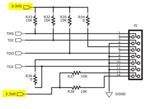
A common problem with the XDS110 adapter is also the power. If you are using both the PMBus adapter and the XDS110 adapter at the same time, make sure you are supply power to the control card correctly. An error like yours might occur since you do not have power properly supplied TO the JTAG 3.3V pins. Provide 3.3V power to the UCD control card via the USB-to-GPIO adapter and then try flashing with the XDS110 via JTAG.
I am using a USB-to-GPIO adapter along with the UCD3138CC64EVM-030 board. I want to edit the code. If I opened the code in Code Composer Studio version 6.1.3,when i debug it ,it asks for ccxml file that is target configuration Which connection should I choose in the connection options, and which board or device should I select? I am new to this field. Guide me, please.
Step 1: Download the Fusion Studio GUI. When you download Fusion Studio GUI, you will have 3 programs that are installed: Fusion Studio Online, Fusion Design Offline and UCD3xxx Device GUI.
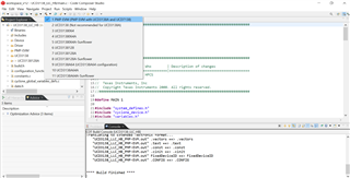
Step 2: You only use Code Composer Studio (CCS) to BUILD your UCD project, not to flash. So, you download the UCD LLC EVM firmware and open the project in CCS. On CCS, you can make any changes to the firmware that you would like. Once you are satisfied with your UCD project, click build and CCS will build the project. Inherently, as a UCD project, CCS will generate a .x0 file in your project build folder. When you click build in CCS for your UCD LLC firmware, a .x0 file will automatically generate. Make sure to select the correct UCD target in the build dropdown.
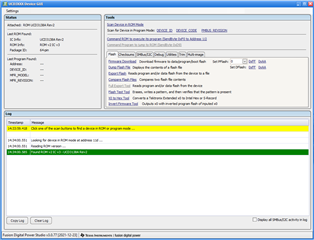
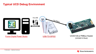
Step 3: Once you have the .x0 file generated, then you will open Fusion Studio UCD3xxx Device GUI. Connect the UCD3138A control card with your computer via the USB-TO-GPIO2 adapter. The USB-TO-GPIO2 adapter communicates via PMBus, not JTAG. Click "Scan Device in ROM Mode" in the GUI. A green "Found ROM..." message should show up in the log. If not, then there is either something wrong with your adapter or your UCD chip.
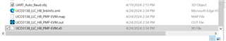
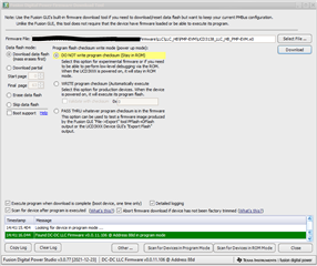
Step 4: Now that your UCD chip is detected in ROM mode, click on "Firmware Download". Navigate to the folder where your .x0 file has been generated and select the .x0 file. Click "Download". The LLC firmware will have successfully flashed onto your UCD3138A when the green "Found DC-DC LLC Firmware..." message shows up. The firmware is now flashed onto your UCD chip and is ready to be used.
Step 5: The Fusion Studio Online is the GUI that allows you to change the loop compensation and other parameters real-time while your UCD is running on hardware. You will need to keep the UCD connected to your computer via the USB-TO-GPIO2 adapter while your UCD3138 is controlling an EVM. Fusion Studio Offline is used when you do not have a UCD connected and allows you to view example UCD projects.
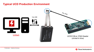
Step 6: Once you are satisfied with your firmware, you can then use JTAG and an XDS110 adapter to flash the final production firmware onto your UCD. This step should only be taken when your firmware is fully tested and will go into an end product. You do not need to use JTAG for debug and testing purposes.
Please let me know if you have any further questions.
If you are ready to flash production firmware, then you can follow the setup using the diagram below. Again, the training labs section on JTAG covers how to flash firmware onto the UCD via JTAG.
I have an doubt in 4th step once we flashed the .xo file(DC-DC LLC Firmware), is it used to reuse again or else we have to flash each time when we open the fusion studio online...,
Every time you modify the firmware and click build, a new .x0 file is generated. You will have to flash this .x0 file via the UCD3xxx Device GUI every time.
Since this question is unrelated to the original question, please post a new thread. Also, when you make a new thread, please let me know what you are confused about the ADC sample code and what you are looking for. Are you confused about how to initialize the ADC? Are you confused how the ADC is used?