This thread has been locked.

If you have a related question, please click the "Ask a related question" button in the top right corner. The newly created question will be automatically linked to this question.

Compiler/UCD3138064EVM-166: UCD3138064EVM166

Part Number: UCD3138064EVM-166

Tool/software: TI C/C++ Compiler

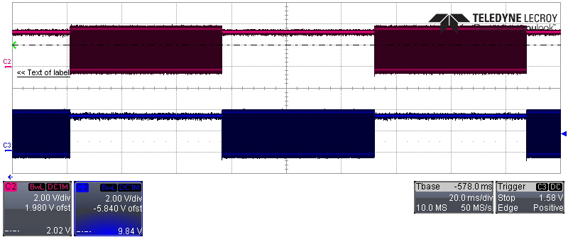
Can anyone please help me to generate pulses in pins DPWM0B and DPWM1B using sensed parameter value. I am including my program below please help me to find out problem in this.

// Initialization

void init_dpwm0(void)
{
Dpwm0Regs.DPWMCTRL0.bit.PWM_EN = 0; //disable locally for init
Dpwm0Regs.DPWMCTRL0.bit.CLA_EN = 0; //default is 1 - use cla
Dpwm0Regs.DPWMCTRL0.bit.PWM_MODE = 3; //normal mode
Dpwm0Regs.DPWMPRD.all = PERIOD; //use .all for all values, make sure scaling matches.

Dpwm0Regs.DPWMEV1.all = 0; // Place EV1 at 132 nS, just out of event update window
Dpwm0Regs.DPWMEV2.all = PERIOD/2; // Does not really matter if you do not use B output
Dpwm0Regs.DPWMEV3.all = PERIOD/2 ; // Does not really matter if you do not use B output
Dpwm0Regs.DPWMEV4.all = PERIOD; // Does not really matter if you do not use B output


Dpwm0Regs.DPWMSAMPTRIG1.all = (PERIOD*3)/4; //500 nS before the end of period

Dpwm0Regs.DPWMCTRL2.bit.SAMPLE_TRIG_1_EN = 1; //enable 1 sample trigger
Dpwm0Regs.DPWMCTRL1.bit.EVENT_UP_SEL = 1; //update at end of period
Dpwm0Regs.DPWMCTRL0.bit.MSYNC_SLAVE_EN =0; // DPWm0 is master

Dpwm0Regs.DPWMCTRL0.bit.PWM_EN = 1; //enable locally

}

void init_dpwm1(void)
{
Dpwm1Regs.DPWMCTRL0.bit.PWM_EN = 0; //disable locally for init
Dpwm1Regs.DPWMCTRL0.bit.CLA_EN = 0; //default is 1 - use cla
Dpwm1Regs.DPWMCTRL0.bit.PWM_MODE = 3; //normal mode
Dpwm1Regs.DPWMPRD.all = PERIOD; //use .all for all values, make sure scaling matches.

Dpwm1Regs.DPWMEV1.all = 0; // Place EV1 at 132 nS, just out of event update window
Dpwm1Regs.DPWMEV2.all = PERIOD/2; // Does not really matter if you do not use B output
Dpwm1Regs.DPWMEV3.all = PERIOD/2; // Does not really matter if you do not use B output
Dpwm1Regs.DPWMEV4.all = PERIOD; // Does not really matter if you do not use B output

Dpwm1Regs.DPWMSAMPTRIG1.all = (PERIOD*3)/4; //500 nS before the end of period

Dpwm1Regs.DPWMCTRL1.bit.EVENT_UP_SEL = 1; //update at end of period
Dpwm1Regs.DPWMCTRL0.bit.MSYNC_SLAVE_EN =0; // DPWm1 is slave
LoopMuxRegs.DPWMMUX.bit.DPWM1_SYNC_SEL =0;//DPWm1 is a slave, sync with DPWM0
Dpwm1Regs.DPWMCTRL0.bit.PWM_EN = 1; //enable locally
}

// Conditions

void poll_adc(void)
{
if(AdcRegs.ADCSTAT.bit.ADC_INT==1)//If the conversion is not complete
{
Ic= AdcRegs.ADCRESULT[3].all;
AdcRegs.ADCCTRL.bit.SW_START = 1; //RESTART
}
}

void rectify_vac(void)
{
t1=Ic;
t2 = (1.2/2.5)*0xfff;
t4 = (0.95/2.5)*0xfff;
t3=(0.1/2.5)*0xfff;

Dpwm0Regs.DPWMCTRL1.bit.GPIO_B_EN = 1;
Dpwm1Regs.DPWMCTRL1.bit.GPIO_B_EN = 1;
Dpwm0Regs.DPWMCTRL1.bit.GPIO_B_VAL = 0;
Dpwm1Regs.DPWMCTRL1.bit.GPIO_B_VAL = 0;
if(t4>=t1>=t2)

{
if(t1>=t2)

{

Dpwm0Regs.DPWMCTRL1.bit.GPIO_B_EN = 0; //now turn on neutral PWM
Dpwm1Regs.DPWMCTRL1.bit.GPIO_B_VAL = 1; //and then drive line always high
}
else
{

Dpwm1Regs.DPWMCTRL1.bit.GPIO_B_EN =0;
Dpwm0Regs.DPWMCTRL1.bit.GPIO_B_VAL = 1; //line drive low
}
}
else
{
Dpwm0Regs.DPWMCTRL1.bit.GPIO_B_EN = 0;
Dpwm1Regs.DPWMCTRL1.bit.GPIO_B_EN = 0;
Dpwm0Regs.DPWMCTRL1.bit.GPIO_B_VAL = 0;
Dpwm1Regs.DPWMCTRL1.bit.GPIO_B_VAL = 0;
}

}

  • Your question has been forwarded to the appropriate engineer.
  • I can't really tell what you are trying to accomplish with your program, so I can't really tell you how to fix it.

    The UCD is designed around a specific way to sense a parameter and control the pulse width on the DPWMs. Here are the steps:

    1. A voltage is sensed on an EADC pin pair
    2. The voltage is compared to a target voltage set on an EADC DAC, generating a digital error value
    3. The error is fed into a PID filter, which compensates for the characteristics of the power supply plant and the load.
    4. The output of the filter is used to control the pulse width of the DPWM.

    There are other options, one for Peak Current Mode, and one for resonant mode (LLC), but the most common approach is as described above.

    We have some video labs which show the basic process step by step here:

    training.ti.com/ucd3138-digital-power-training-series

    Setting everything up for a specific topology can get very complicated, so it's best to start with an EVM code that is closest to your target system and go from there. The UCD peripherals are very powerful and configurable, which means they are also very complicated. Personally I'd never start from scratch. And I did start from scratch when the UCD first came out. Except for Peak Current Mode. That I had to get from the designers.

    If you need to do something outside these descriptions, please let me know.
  • Thank you for your kind reply. I am trying to sense the voltage in AD03 pin, does the command is proper for sensing this.

  • If you use the ADC, you're not using the strengths of the UCD. You have to use the EADC/Filter/DPWM combination to take advantage of the UCD. If you use the ADC, you've just got a not very good DSP. If you use the EADC/Filter/DPWM, you can run 3 separate PID control loops at 2 MHz, without using any processor MIPs at all.

    Now we do use the ADC as part of the control loop on PFC. We measure the output voltage at 10 KHz for the voltage loop, and we measure the AC input at 50 KHz. We multiply the AC input value times the voltage loop output and put that into an EADC DAC to set the current target. We use the fast EADC/Filter/DPWM sequence to control the current loop, which is the only thing that needs to be really fast on a PFC.

    If that's what you want to do, see our PFC EVM here:
    www.ti.com/.../UCD3138PFCEVM-026

    If there's something else you want to do, maybe I can help you use the hardware loop on the UCD.
  • Thanks a lot. Can you please check and tell me whether DPWM initialization is correct if I want to use only A pins.
  • I don't like getting into the business of reading code and telling whether it is correct. It really needs to be tested. And it needs to be tested relative to some kind of a spec. You still haven't given me any detail on what you are actually trying to do, so I'll keep guessing. Are you trying to do a bridgeless PFC, and control the switches which are turned on full time for half the AC cycle, and modulated for the other half?

    If so, I suggest looking at the PFC EVM code, because it supports that. There should be a bridgeless #define - look at code that is compiled when that #define is defined.

    Otherwise, I need some more detail on what you are trying to do. What kind of pulses are you trying to generate on the DPWMs? I could make a long list of pulse types.
  • Thanks a lot. Yes this program is for bridgeless PFC converter. The alternate (positive and negative end) switches will be on continuously for 180 degree and operate at high frequency for rest 180 degree. This signal can only be generated with sensed sine voltage (to detect positive and negative half). I have attached the switching waveform required in pins DPWM0A a nd DPWM1A with this post.

  • My program is fine but the problem I have when comparing sensed variable Ic with some constant value =0.7.

    if(AdcRegs.ADCSTAT.bit.ADC_INT==1)//If the conversion is not complete
    {
    Ic= AdcRegs.ADCRESULT[3].all;
    AdcRegs.ADCCTRL.bit.SW_START = 1; //RESTART
    }

    void rectify_vac(void)
    {
    t1=(Ic/2.5)*0xfff;
    t2 = (0.7/2.5)*0xfff;

    if(t1>=t2)
    {
    Dpwm0Regs.DPWMCTRL1.bit.GPIO_B_EN = 1;
    Dpwm1Regs.DPWMCTRL1.bit.GPIO_B_EN = 0;
    }

    else
    {
    Dpwm0Regs.DPWMCTRL1.bit.GPIO_B_EN = 0;
    Dpwm1Regs.DPWMCTRL1.bit.GPIO_B_EN = 1;
    }

    }


    This time it is always giving result for 'else' function, 'if' function is not executing properly. Please help me .
  • It looks like you're sort of using floating point. You really need to do everything in integer mode, so it will run faster, and be compatible with the ADC output. For execution speed, you really need to figure out the comparison value as the ADC output value.

    I'm not sure what you've got coming in. Normally we have line and neutral, and we need to subtract the two of them and compare the difference. When we do that, invert the number for one direction so it's always positive. And we use a polarity bit to tell us which half cycle we are in. Suppose you've got your divider set up so that full range on your ADC is 500 volts. Since the ADC voltage range is 2.5 volts, this means a voltage divider of 200.

    If you take 4095 (for full range ADC output) and divide it by (2.5*200) for input that will give full range ADC output, you will get the constant for converting bits to ADC value. It's easy in this case, it ends up being 8.

    So then you can take your voltage at which you want to switch, and multiply it times 8, and then use that as your comparison value for the ADC value. Or you can embed all those calculations into a #define and use it for a comparison. Just make sure that you do all the calculations in float, and then cast the whole thing to an int before the comparison.
  • Does this mean my parameters for comparison should be like as below:

    t1=Ic;
    t2 = ((0.7/2.5)*0xfff)*8;
  • I have used only one sensor to sense the voltage. Therefore, to implement the control I need to use integer reference for comparison. Can you please write in terms of my parameters t1 (for sensing value) and t2 (for integer value) the conversion equation for better understanding. Looking forward to hear back from you. Thank you.
  • I'm sorry, but fixing your program at that level is outside my charter of device support. I suggest again that you just do a simple if statement like this:

    if(adc_value < adc_value_which_matches_voltage_I_want_to_compare)

    If I'm not sure if my calculations of the target adc value are not right, I just put various voltage on there and see what value I get. It's always a good check.