This thread has been locked.

If you have a related question, please click the "Ask a related question" button in the top right corner. The newly created question will be automatically linked to this question.

CCS/FDC2214EVM: How to program the on-board MSP430F5528

Part Number: FDC2214EVM
Other Parts Discussed in Thread: MSP430F5528, MSP-EXP430F5529LP, MSP-FET, MSP-EXP430G2ET

Tool/software: Code Composer Studio

Hey guys,

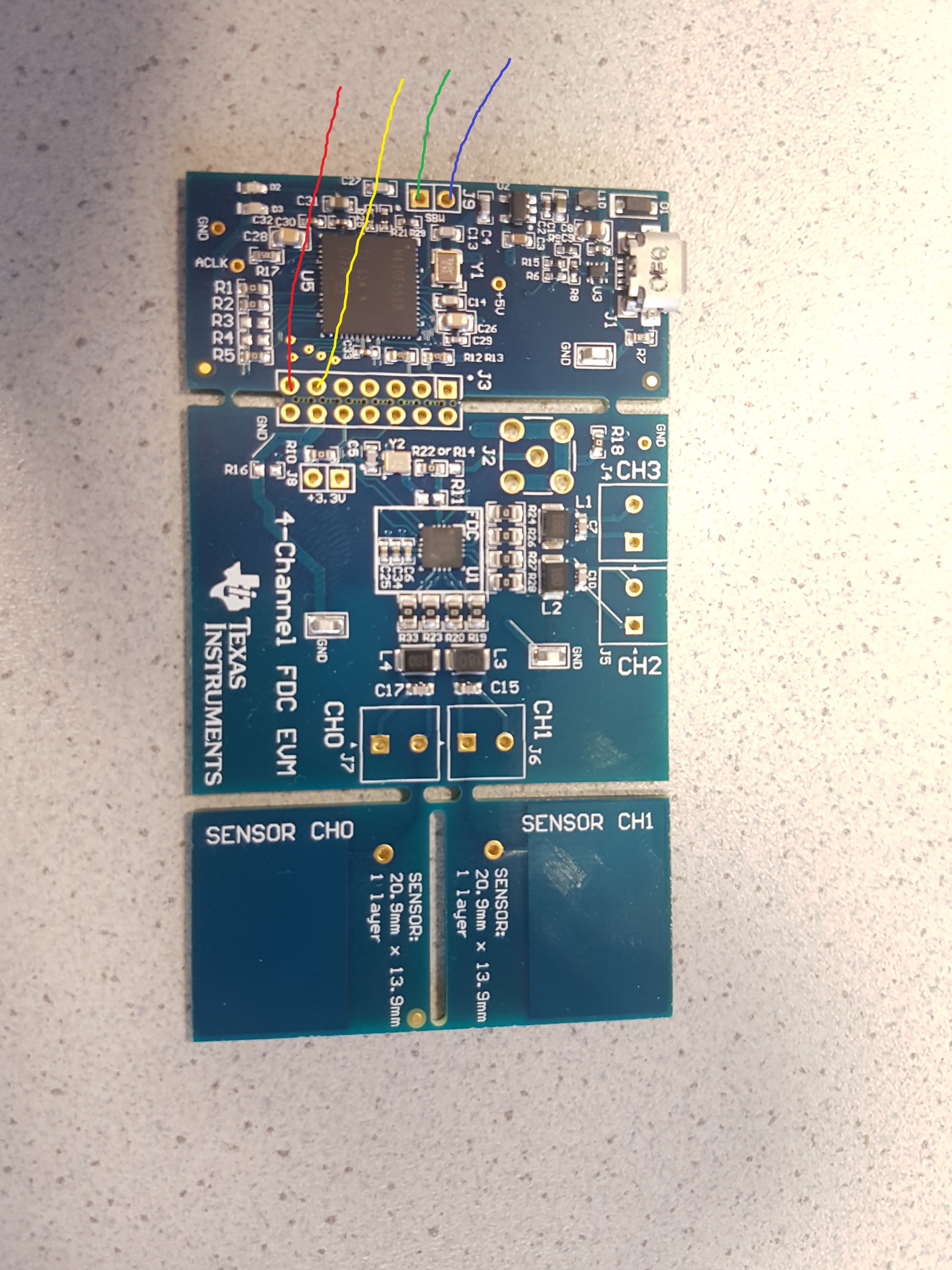
currently i got the FDC2214EVM with a MSP430F5528 on it. Usually it should be possible to program it.

Last time i asked a question, someone told me i got no JTAG-Interface, so it is not possible. My question is, what i have to do  to be able to program the EVM? My goal is to get the signals of the CH0 and CH1 Capacitive Sensors as an input with CCS. Do i have to buy a completely different EVM to program it or can i just add some hardware to it.

If i need to add some hardware, are there any instructions which and how to install them?

Thanks for your answers

  • Hi Marius,

    Thanks for your detailed post. The FDC2214EVM does have a JTAG interface where you can solder a header for easier access. Looking at the FDC2214EVM's schematic, J9 brings out the JTAG SBW signals, Reset and Test. If you have a MSP-FET debugger, you could use short jumper wires to connect to these SBW signals and VCC target (or supply) on the MSP-FET and GND for programming the MSP430F5528. An alternative to the MSP-FET would be using the on-board debugger (part above the isolation jumpers) on one of our newer LaunchPads, such as the MSP-EXP430F5529LP, to program your EVM.

    Since you're interested in capacitive touch, have you seen our FRAM MCUs with CapTIvate technology? There's a Design Center GUI as well as a hardware development kit that may be easier for your development. The FDC2214EVM may be best for your application but I wanted to make you aware of CapTIvate as well.

    Regards,

    James

  • Hi James,

    Thanks for your answer. So to program my FDC2214EVM i need to buy a MSP-FET and some jump wires first? If i got these two things and connect it with my FDC2214EVM it should be easy to program it with CCS? I usually dont work a lot with MCU's, so my question is also, if i got the hardware with the wires, is it easy to install it on my MCU or are there any instructions where i need to put the wires on the EVM and also on the MSP-FET?

    Regards,
    Marius
  • Hi Marius,

    Marius Lorenz said:
    Thanks for your answer. So to program my FDC2214EVM i need to buy a MSP-FET and some jump wires first? If i got these two things and connect it with my FDC2214EVM it should be easy to program it with CCS?

    Yes. You'll need to solder a header to J9 on the FDC2214EVM. Then, you can use jumper wires to connect J9 to the MSP-FET pins, which you can access after removing the 14-pin cable. For the correct connections, you'll need to refer to the MSP430 Hardware Tools User's Guide and the FDC2214EVM's schematic. Basically, you'll need the two SBW connections plus GND and the FDC2214EVM's VCC (connected to VCC target on the MSP-FET).

    Two options. If you plan on future debugging and programming with your own custom boards, I would recommend purchasing the MSP-FET. It supports the widest range of features and supports all MSP430 devices. However, if you don't plan on much programming, you could order one of our evaluation modules like the MSP-EXP430G2ET and leverage it's on-board debugger (that supports SBW programming) to program the EVM. You can read more about this functionality in the MSP430G2553 LaunchPad™ Development Kit (MSP-EXP430G2ET) User's Guide in Section 2.6 Using the eZ-FET Debug Probe With a Different Target.

    I hope this helps.

    Regards,

    James

  • Hi James,

    thank you so much. You helped me a lot with this topic as being a newcomer in MCU. Maybe you got a link for the right header? I need to present my boss a list of the components that are left for the project. You are really doing a great job!

    Regards,
    Marius
  • Hi Marius,

    Thanks for your kind feedback! Looking at page 50 in the FDC2114 and FDC2214 EVM User’s Guide, I see that the part number for the J9 header is TSW-102-07-G-S (made by Samtec) and is described as "Header, TH, 100mil, 2x1, Gold plated, 230 mil above insulator".

    Since the through-hole spacing on J3 is the same (100mil), you could solder another 2-pin header on pins J3.11 and J3.13 or J3.12 and J3.14 to easily connect your jumper wires to GND and +3.3V on the FDC2214EVM.

    Thus, you'll probably want to order at least two of these headers.

    Regards,

    James

  • Hi James,

    thanks for your answer, helps me a lot. I'll do a summary of all we got. I will buy the MSP-FET, 2 of the headers, and jumper wires. I'll solder one of the header at J9 and one at J3. Then i connect my J9 of the EVM with the wires to the SBW, VCC and GND of the MSP-FET. The header on J3 on EVM is connected with GND,SBW and VCC of the EVM,right? If i should have problems with the connections, can i take photos and show it here?
  • J9: SBW Reset and Test

    J3: +3V3 and GND

    Marius Lorenz said:
    If i should have problems with the connections, can i take photos and show it here?

    Sure.

    Regards,

    James

  • Hey James,

    i got my MSP-FET now. It currently looks like this. The 2 2-pin header for J9 and J3 are also ordered. Can you maybe just draw in where i put my wires from the EVM to the FET? I'll show you how i understood it should be. I go out from J9 and J3.13 J3.11 from the EVM. Then i connect the 4 wires to the J3 from FET. But i dont get which wire is the right to connect with the FET.

    Regards,

    Marius

  • Hi Marius,

    Please refer to Figure 2-3 in the MSP430 Hardware Tools User's Guide for the MSP-FET connections. If you plan on powering the EVM from the MSP-FET, you'll want to use "VCC_TOOL". If you're using an external power supply, then use "VCC_TARGET" instead. Refer to the diagram underneath the MSP-FET's housing for the pin versus connector key orientation. Besides supply voltage, you'll want to connect to Pin 1, 7, and 9.

    Regards,

    James

  • Hi James,
    thanks. I nearly understood all connections now. Only one left are GND and 3.3V from the EVM. Where do i put them on the MSP-FET? Pin 1 and 7 are 100% clear and also is J1/J2. And which connection is number 9?

    Regards,
    Marius
  • Marius Lorenz said:
    thanks. I nearly understood all connections now. Only one left are GND and 3.3V from the EVM. Where do i put them on the MSP-FET? Pin 1 and 7 are 100% clear and also is J1/J2. And which connection is number 9?

    Please see my earlier reply about powering the EVM and refer to the Figure above for identifying the pins.

    Regards,

    James