This thread has been locked.

If you have a related question, please click the "Ask a related question" button in the top right corner. The newly created question will be automatically linked to this question.

CCS/TIDA-00721: Unknown device

Part Number: TIDA-00721
Other Parts Discussed in Thread: MSP-FET, MSP430G2403, RF430CL330H

Tool/software: Code Composer Studio

Hello All;

I have problem with programmed the board, 

The code built well without any error, but when I tried to upload/debug to the device I got: MSP430: Error connecting to the target: Unknown device

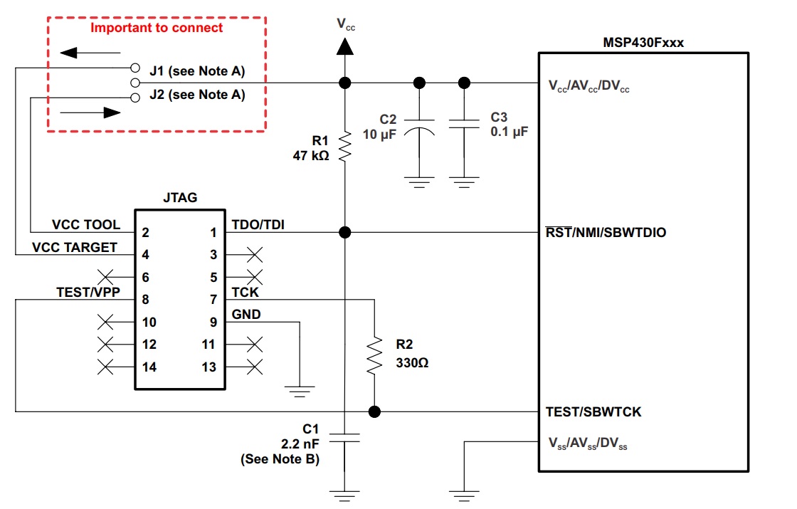
I doubled checked with hardware connections, all seems fine, VDD, GND , SBWTDIO and SBWTCK connected to TJAG 

I use CCS9.

Regards

  • I mean to JTAG :)
    Also, I use MSP-FETFlash programmer. I change the Microcontroller and gave the same error, I also update the driver but also gave the same error
  • Hey Ennng,

    You should be able to follow the connection listed on the schematic: www.ti.com/.../tidrm48.pdf

    Also, Make sure you are connecting the SBWTCK pin to the MSP-FET Test pin with a weak pull-up to TCK. Figure 2.2 of the Hardware tools users guide shows the correct SBW connections for the MSP430G2xx devices: www.ti.com/.../slau278ae.pdf

    If all that is correct, I would double check the device the CCS project is being built for and the MSP430 on the patch. I believe they should both be the MSP430G2403.

    Finally, How did you connect to the patch? The flex PCBs are sometimes difficult to sold to and can more easily be damaged. It might work better to connect the JTAG to a head and somehow press it against the pads.

    Thanks,
    JD
  • Hi JD;

    Thank you very much for your answer.
    Regarding to schematic, yes I use exactly the same and even use the pcb design that provide by TI, exactly the same, but one thing (C6) I didn’t amount it! I think this shouldn’t affect during programming the Microcontroller?

    Regarding to test pin, in the pcb design, they don’t use it, just connect the clock pin of the programmer straight to the clock pin of the Microcontroller. Even in the Figure 2.2 said if don’t connect you don’t need the test pin? Is this important? Shall we try it? I just use the pcb reference design from TI!
    Actually I use both rigid and flexible pcb and all gave the same error when debug? Unknown device?
    Is there any sitting or configuration that I need to check in the CCS?
    Thank you for your help
  •  Hello Dear;

    Yes, today I tried  the correct SBW connections for the MSP430G2xx device from the link, I connected Test pin with a weak pull-up to TCK, but got the same error!

    please have a look to the setting and configurations, probably I miss something!  thank you for your help.

  • one more think please, I didn't mount ( C6 ) in schematic! is this affect?
    Also, I didn't mount the crystal since the TI reference design don't use it! They use internal clock, but not sure about the external crystal is it required during programming the Microcontroller or not!
    Regards
  • Ennng,

    Thanks for confirming the SBW Programming circuit. C6 just looks like a filter cap, so as long as you have some filter caps on VCC you'll be fine. As for the crystal, this is not required for programming.

    Also, your CCS setting look correct to me.

    I'm guessing it's a hardware issue at this point. Is the board being powered? Is the MSP430 mounted in the correct orientation?

    Thanks,
    JD
  • Hello DJ
    Thank you very much again for your reply,
    Actually I mounted the Microcontroller on two boards, first I thought that the Microcontroller is faulty and mount another board and got the same error for both, the orientation is OK and based on the reference design from TI the first pin (dot) should be in the bottom left corner as on PCB design. I also checked the voltage across the Microcontroller and found that 3.3v supplied from MSP FET programmer (V tool)
  • Hello JD;

    Please see figures of  JTAG connections. Is this OK!

     Yellow (VDD), Green (GND), Blue (TDIO) and Purple (TCK), are these OK?

    I also tried with puled resistor and test pin connected to TCK as shown in pdf document (figure 2.2)

    still unknown device !

    Regards

  •     I am sorry  for more post, I just tried a lot of things but still nothing! same error.

    I just change in Debug  configurations, please see figures, when hit debug button the red LED on the programmer start blinking and then stay ON,

    when I got error massage I cancel and then the only green LED ON, and no red LED.

  • Ennng,

    In your picture or the MSP-FET connector, I see you are connected to TCK instead of Test/VPP. Could you please switch this and try again?

    Also, I'm going to be traveling the next 2 days, So I will get back to you on monday if you are still needing feedback or someone else may jump in.

    Thanks,
    JD
  • Hi JD;
    Thank you and hope all the best for your travelling.
    I tried your suggestion but still gave same error.
    - I connected to Test/VPP directly, also through small resistor.
    - I connected to TCK directly (as in the TI reference design)
    - I connected to both TCK and Test/VPP (as in Figure 2.2, pdf MSP430G2xx devices)
    all gave this error !
    Regards
  • Hello;

    Is this mean the Microcontroller has been programmed ! because when I hit the flash button it gave this message, nothing-else like loaded or successfully..

    if yes why then I didn't get any read on the phone! (app from TI in the document)

    Regards  

  • Hello;

    Is the last photo means that the chip has been programmed!

    I also tried different method to flash and got different message! Flash -> select program to load -> then I choose .Hex file

    then LED on the programmer start flashing and got message on the Console (some numbers XXX byte were programmed !) is this mean the chip is programmed! because different message from previous !

    because when trying to search for the tag (board) from NFC reader, and NFC phone app, nothing is detected! 

    Regards

  • Hey Ennng,

    Is that all the console window shows? That looks like it's programmed to me, but I would expect the console window to possibly show more.

    Can you tell at all if the device is running the firmware? Are there any LEDs or test points that you could toggle to try and blink to confirm that you are now correctly programming the device?

    Thanks,
    JD
  • Hi JD;
    Thank you again for your reply.
    When I flash the code it gave a lot of messages built...whatever and end up with that message shown in the last figure. I follow the link (upload code int MSP) and gave me the same.
    circuitdigest.com/.../getting-started-with-msp430-using-code-composer-studio
    I think the Microcontroller being programmed as you said but the NFC on board did not detected at all, I tried different NFC reader, Mobile NFC enabled.
    There are no LED on board or testing point as I took the design from TI.
    Also, there isn’t any external crystal as TI reference said don’t used it? I think they active the internal one!
    Please any help or suggestion! Some one said to me is that you need to change C5 in schematic (tuning with antenna ) but I mean this already done by TI I guess so I used exactly the same capacitance value!
    By the way I use rigid PCB as I still have issue with Flexible, one, is this affected the NFC detected? since TI reference use flexible PCB!
    Regards
  • Hey Ennng,

    Glad to hear that you are successfully programming the MSP430. I'm not sure why the NFC side isn't working, but the tuning is very important. Using a different type of material for the PCB or different copper thickness can deffinantly change the needed tuning values. Unfortunantly, that's about as much as I know on the NFC side these days.

    Since you are able to program the MSP430, I think we should say this thread is resolved. Please create a new thread on this design and the RF430CL330H and our team supporting NFC will try to assist you. Feel free to link to this one if they need background.

    Thanks,
    JD