This thread has been locked.

If you have a related question, please click the "Ask a related question" button in the top right corner. The newly created question will be automatically linked to this question.

Compiler/DAC7750: DAC7750 write register

Part Number: DAC7750

Tool/software: TI C/C++ Compiler

Hi,
I am implementing an application that will set a DAC code on DAC7750 and reading voltage output from SDO. But whichever DAC value of code I write in my program I always get 0 V reading from SDO of the DAC7750 chip. Below is the main part that sets dacValue 4095 for the 12 bit DAC7750.
where dacValue is set with:
dacValue = 4095; //test value​
DAC7750_SetOutValue (dacValue);
  • 	dacValue = 4095; //test value
    	DAC7750_SetOutValue (dacValue);
        ......
    }
    
    
  • The purpose here is to set a DAC code on DAC7750 and reading voltage output from SDO. But whichever DAC value of code I write in my program I always get 0 V reading from SDO of the DAC7750 chip. Below is the main part that sets dacValue 4095 for the 12 bit DAC7750. I have attached the DAC7750.c (function implementations for DAC write register, configurations), DAC7750.h (register addresses defines), spi.c and spi.h (SPI library used to communicate on Raspberry PI).

    Please see the above code snippet and attached code files (.c and .h) in the first message
    dacValue is set with:
    dacValue = 4095; //test value​

    DAC7750_SetOutValue (dacValue);

  • Please let me know why I am getting 0 V reading from SDO of the DAC7750 chip and help me in resolving the errors that might be causing this.

  • Jubayer,

    Reza or I will provide you with an update by tomorrow. In the meanwhile, it would be helpful to expedite this to actually see the transactions on the SPI bus instead of reading code. Even if the code is perfect - there is still the possibility for a board-level analog problem which we would not detect from reading code.

  • Hello Jubayer,

    Are you able to successfully read back data from any other registers? As an example, can you read back the data from the control register (addr 0x55) to confirm the correct setup of the DAC?

    Also, what is the status of the CLR pin on your board?

    Regards,

    Reza

  • When I read from the control register (addr 0x55) the read back data is: 0xdc (220 in decimal)

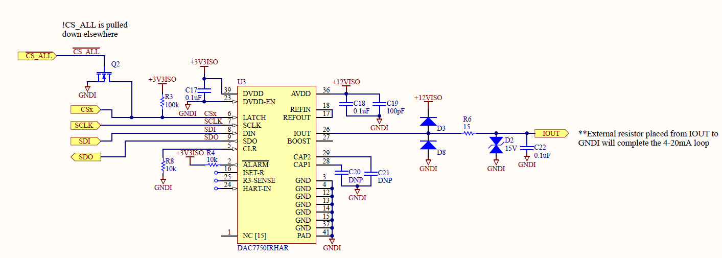
    CLR pin is connected to ground with 10k resistor, so it's always connected to ground GND.

    Additionally, status register is also sending back 0xdc (220 in decimal).

    I have also  attached the diagram of circuitry.

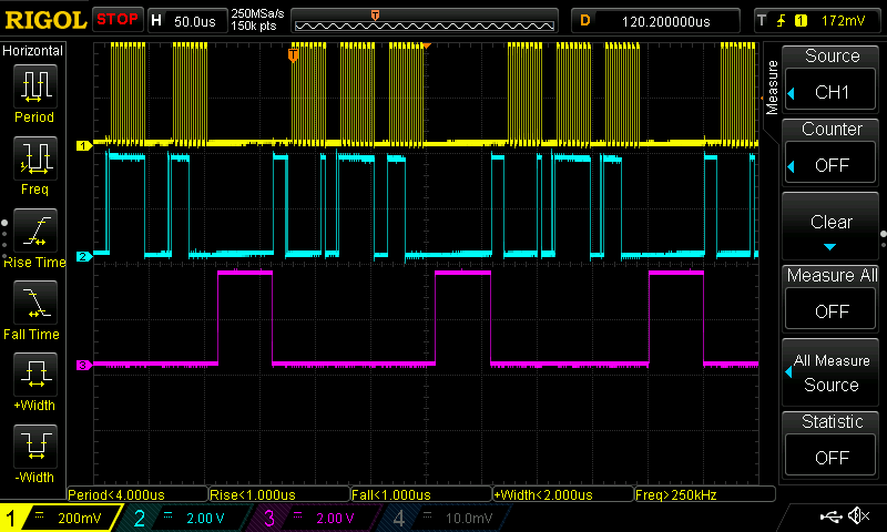
  • I have attached the waveforms for clock (SCLK), DIN and LATCH (CS1/DAC1 for my example, as we are using a multiplexer to select which DAC to write to out of 12 DACs).

    1. The yellow waveform ====  clock CLK

    2. Blue waveform ==== data in (DIN)

    3. Purple waveform ==== LATCH (Chip select CS1 in my example)

  • Hello Jubayer and thanks for the additional information. I have 4 comments below to help figure out the issue.

    1. Device power up: Please confirm that device powers up correctly by measuring the AVDD current. At power up, is should be approx 2mA. You can also measure VREF after power up to confirm that it is 5V.

    2. After correct power up, configure and write to DAC like you do in the code above. Does the output current change? If not there likely is an issue with the SPI frame. As a result the readback will also not work correctly.

    3. I notice a large glitch approx 2V on the LATCH line of the SPI frame. LATCH should only go high after 24 SCLK edges for a valid write operation. The DAC7750 unconditionally latches the data after the last 24 SCLK bits before a rising latch signal. The glitch in the middle of the latch frame could unintentionally result in wrong data being written to the SPI shift register.

    4. The 0xDC data you readback from the control and status registers is incorrect, again implying a possible issue with the SPI read/ write frames. Please try to eliminate the glitch in the SPI frame, retest the part and share the result afterwards. 

    Thanks,

    Reza

  • I have fixed the SPI frame implementation in the code, now it seems working. For the DAC value of 0x0000 I get 4 mA and DAC value of 0xFFF0 I get 20 mA. I also get status register value as 0.

    I have attached the SPI transactions below:

  • Great! Are you also now able to read back the data from the registers? Please note that reading back the SPI registers requires two SPI frames. The first frame specifies the read command and which register to read. The second command is a NOOP and the data is clocked out of the SDO pin during the NOOP frame. 

    Regards,

    Reza

  • Thanks. Yes, that part works as well.

    Regards

    Jubayer

  • Hello Jubayer Ahmed,

    We are developing an application with DAC7750 with ATmega128A-AU on CodeVision.

    The codes that you've shared are functional? 

    Did you conclude your firmware?

    We don’t have much time to implement the DAC7750 on our code, so any help is welcome!


    Regards,

    Márcio