Part Number: TDC1000-C2000EVM
Other Parts Discussed in Thread: TDC1000,
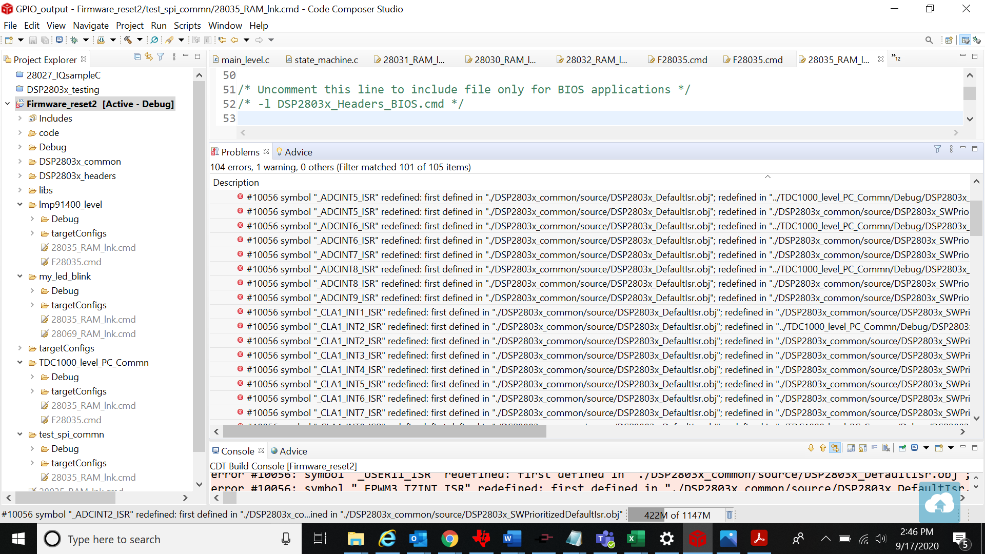
Tool/software: Code Composer Studio
Hello,
I have been working on a project with the TDC100-C2000EVM to identify when there is a change in liquid concentration inside a vessel. In my test set up, I have two ultrasonic transducers connected across from each other. I can see a change in the Time of Flight (TOF) in real time when I turn on the TDC1000-C2000 GUI and start the graph.
My goal for this project is to write the values out from the C2000 microcontroller to an Arduino to read the TOF values via the Arduino’s serial monitor feature. I am having trouble figuring out how to have the TDC1000 and the C2000 communicate to each other. I purchased the XDS110 Debug Probe and downloaded code composer studio to try to debug the C2000 so that I could get this to work.
There are 8 GPIOs available to hook up to directly. Each has a specific output peripheral it can be switched to. Below is the code I made for this:
// Enable GPIO0 as EPWM1A - ePWM1 output A (O)
           //
 GpioCtrlRegs.GPAPUD.bit.GPIO0 = 0;   // Enable pullup on GPIO0
 GpioDataRegs.GPASET.bit.GPIO0 = 1;   // Load output latch
 GpioCtrlRegs.GPAMUX1.bit.GPIO0 = 1;  // GPIO0 = EPWM1A - ePWM1 output B(O)
 GpioCtrlRegs.GPADIR.bit.GPIO0 = 1;   // GPIO0 = output

       //
// Enable GPIO1 as EPWM1B - ePWM1 output B (O)

                    //
GpioCtrlRegs.GPAPUD.bit.GPIO1 = 0;   // Enable pullup on GPIO1 GpioDataRegs.GPASET.bit.GPIO1 = 1;   // Load output latch
GpioCtrlRegs.GPAMUX1.bit.GPIO1 = 0;  // GPIO1 = EPWM1B - ePWM1 output B (O)
GpioCtrlRegs.GPADIR.bit.GPIO1 = 1;   // GPIO1 = output

       //
// Enable GPIO3 as EPWM2B - ePWM2 output B (O)
                            //
GpioCtrlRegs.GPAPUD.bit.GPIO3 = 0;   // Enable pullup on GPIO3
GpioDataRegs.GPASET.bit.GPIO3 = 1;   // Load output latch
GpioCtrlRegs.GPAMUX1.bit.GPIO3 = 0;  // GPIO3 = EPWM2B - ePWM2 output B (O)
GpioCtrlRegs.GPADIR.bit.GPIO3 = 1;   // GPIO1 = output

       //
// Enable GPIO7 as EPWM4B - ePWM4 output B (O)
                                     //
GpioCtrlRegs.GPAPUD.bit.GPIO7 = 0;   // Enable pullup on GPIO7
GpioDataRegs.GPASET.bit.GPIO7 = 1;   // Load output latch
GpioCtrlRegs.GPAMUX1.bit.GPIO7 = 0;  // GPIO7 = EPWM4B - ePWM4 output B (O)
GpioCtrlRegs.GPADIR.bit.GPIO7 = 1;   // GPIO7 = output

       //
// EGPIO30 only has input peripherals

//  GpioCtrlRegs.GPAPUD.bit.GPIO30 = 0;   // Enable pullup on GPIO30
//  GpioDataRegs.GPASET.bit.GPIO30 = 1;   // Load output latch
//  GpioCtrlRegs.GPAMUX1.bit.GPIO30 = 0;// GPIO30 = GPIO30
// GpioCtrlRegs.GPADIR.bit.GPIO30 = 1;   //

//
// Enable GPIO31 as CANTXA - eCAN-A transmit (O)
                                         //
GpioCtrlRegs.GPAPUD.bit.GPIO31 = 0;   // Enable pullup on GPIO31
GpioDataRegs.GPASET.bit.GPIO31 = 1;   // Load output latch
GpioCtrlRegs.GPAMUX2.bit.GPIO31 = 1;  // GPIO31 = CANTXA - eCAN-A transmit (O)
GpioCtrlRegs.GPADIR.bit.GPIO31 = 1;   // GPIO31 = output

//
// Enable GPIO32 as ADCSOCAO - ADC start-of-conversion A (O)
                                                 //
GpioCtrlRegs.GPBPUD.bit.GPIO32 = 0;   // Enable pullup on GPIO32
GpioDataRegs.GPBSET.bit.GPIO32 = 1;   // Load output latch
GpioCtrlRegs.GPBMUX1.bit.GPIO32 = 4;  // GPIO32 = ADCSOCAO - ADC start-of-conversion A (O)
GpioCtrlRegs.GPBDIR.bit.GPIO32 = 1;  // GPIO32 = output


// Enable  GPIO33 as GPIO33 = ADCSOCBO - ADC start-of-conversion B (O)
                                                     //
GpioCtrlRegs.GPBPUD.bit.GPIO33 = 0;   // Enable pullup on GPIO33
GpioDataRegs.GPBSET.bit.GPIO33 = 1;   // Load output latch
GpioCtrlRegs.GPBMUX1.bit.GPIO33 = 4;  // GPIO33 = ADCSOCBO - ADC start-of-conversion B (O)
GpioCtrlRegs.GPBDIR.bit.GPIO33 = 1;  // GPIO33 = output
Once these GPIOs are set to their respected output types (ePWM, CANTX, ADC start-of-conversion), I don’t know what these values are outputting when reading them on the Arduino. If I disconnect the transducer from TX1, the value does not change. If I comment out the GPIO code, I read 0 on the Arduino. I am reading something from the board, but don’t know what.
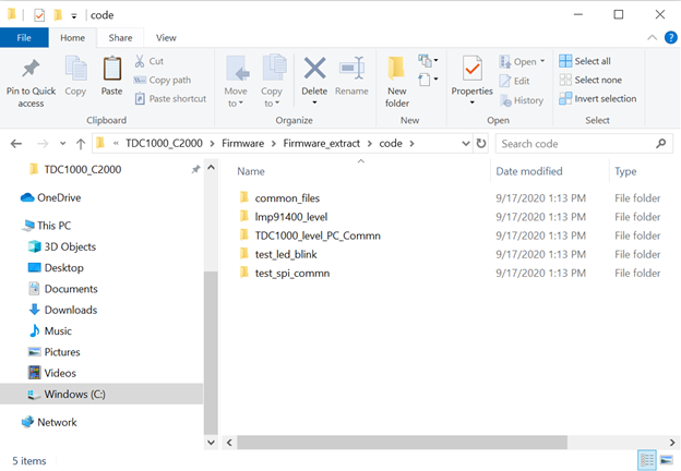
Under the source code: "C:\Program Files (x86)\Texas Instruments\TDC1000_C2000\Firmware\TDC1000_C2000EVM_FW-Source-v1.42.zip".
I was able to find a file that said main_level.c. Below is a snippet of that code.
void TI_LMP91400_reg_init(void)
{

  // 1MHz test cell (green)
#if 0
    TI_LMP91400_SPIWriteReg(TI_LMP91400_CONFIG0_REG, 0x44); // 4pulses
    TI_LMP91400_SPIWriteReg(TI_LMP91400_CONFIG1_REG, 0x41); // -> 44 to 40 (1stop)
    TI_LMP91400_SPIWriteReg(TI_LMP91400_CONFIG2_REG, 0x04); // tx2 is 04, tx1 is 0
    TI_LMP91400_SPIWriteReg(TI_LMP91400_CONFIG3_REG, 0x0C); // enable blanking, 320mv threshold
    TI_LMP91400_SPIWriteReg(TI_LMP91400_CONFIG4_REG, 0x5F); // 5e (group) -> 1e (edge mode)
    TI_LMP91400_SPIWriteReg(TI_LMP91400_TOF1_REG, 0x40);
    TI_LMP91400_SPIWriteReg(TI_LMP91400_TOF0_REG, 0x1E);
    TI_LMP91400_SPIWriteReg(TI_LMP91400_ERROR_FLAGS_REG, 0x01);
    TI_LMP91400_SPIWriteReg(TI_LMP91400_TIMEOUT_REG, 0x23);
    TI_LMP91400_SPIWriteReg(TI_LMP91400_CLOCK_RATE_REG, 0x01);
#endif
}
I am not sure what this TI_LMP91400 is but this is the only time I have seen the TOF0, TOF1 and other registers from the TDC1000. I need to figure out how to get these registers to output from the GPIOs.
If there is a better way to output these values, please let me know.
Thanks,
Colin