This thread has been locked.

If you have a related question, please click the "Ask a related question" button in the top right corner. The newly created question will be automatically linked to this question.

LM25575 inverting buck-boost mode

Other Parts Discussed in Thread: LM25575

Hello,

I am designing a +/-12VDC supply based on LM25575 converters used in cascade. The topology consists to create a +12V from 24VDC (coming from PLC backplane). From the +12V we create the -12V by using the LM25575 converter in inverter mode.

The topology and peripherical components comes from the results of the WEBENCH designer tool. However, when I want to simulate the circuit, the -12V polarity doesn't work.

So, I would like to know if the problem comes from the topology or is it a limitation of the model ?

  • Hi Alexandre,

    We are looking into your request now and will get back to you shortly.

    Thanks,

    Anston

  • Hello,

    Would you please share your schematic and BOM simulated? If required, we could involve the engineers working in the Webench department as well.

    Regards,
    Akshay

  • Hello,

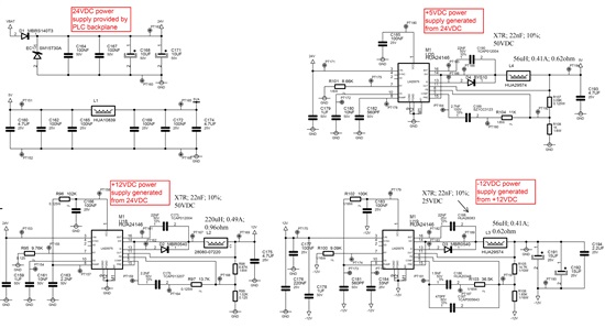
    Please find hereunder the schmematic issued from Webench designer :

    The TI-TINA file is the following :

    0045.1385.Power_supply_testbench.TSC

    and the associated BOM is :

    2112.2425.BOM_PS_management.txt
    #	Quantity	Label	Value	
    1.	1	R8	 1.02k
    2.	1	C26	 1.5n
    3.	1	R13	 1.65k
    4.	1	C12	 100n
    5.	1	C20	 100n
    6.	1	C23	 100n
    7.	1	C4	 100n
    8.	1	C8	 100n
    9.	1	C9	 100n
    10.	1	R10	 102k
    11.	1	R5	 102k
    12.	1	C15	 10n
    13.	1	C2	 10n
    14.	1	C10	 10u
    15.	1	C11	 10u
    16.	1	R4	 11k
    17.	1	R9	 13.7k
    18.	1	R12	 14.7k
    19.	1	R3	 1k
    20.	1	C1	 1u
    21.	1	C13	 1u
    22.	1	C21	 1u
    23.	1	C14	 2.2n
    24.	1	C17	 2.2n
    25.	1	C6	 2.7n
    26.	1	C19	 220n
    27.	1	L2	 220u
    28.	1	C16	 22n
    29.	1	C25	 22n
    30.	1	C5	 22n
    31.	1	V1	 24
    32.	1	R2	 3.09k
    33.	1	C24	 33n
    34.	1	R14	 36.5k
    35.	1	C18	 4.7u
    36.	1	C7	 4.7u
    37.	1	C22	 470p
    38.	1	C27	 470p
    39.	1	C28	 470p
    40.	1	C29	 470p
    41.	1	C3	 560p
    42.	1	L1	 56u
    43.	1	L3	 56u
    44.	1	R1	 8.66k
    45.	1	R7	 8.87k
    46.	1	R11	 9.09k
    47.	1	R6	 9.76k
    48.	1	U2	 BYS10
    49.	1	D1	 DMBR0540T3
    50.	1	D1	 DMBR0540T3
    51.	1	U1	 LM5575_TRANS
    52.	1	U3	 LM5575_TRANS
    53.	1	U4	 LM5575_TRANS
    54.	1	V12m	
    55.	1	V12V	
    56.	1	V5V	
    

    Thanks for your reactivity and your support,

    Alexandre Penaud

  • Hello Alexandre,

    It looks like you are trying to use TINA to simulate the model. I am going to have to involve the modeling engineers to take a look at why the sim is not working. As such I don't see anything blatantly wrong with the design. Laying it out properly would be very important.

    Regards,
    Akshay

  • Hi Alexandre,

    I believe the current TINA model for this was made for Buck topology only.

    Because of the way SPICE sims specially recognize a node 0 as a global GND, even in subcircuits, any internal IC references to 0 in a model make it so its GND referenced, so if in an inverting Buck Boost topology where the IC is referenced to another voltage, the simulation would not function properly.
    So its not a problem with the actual design, its a model issue.

    Best regards,
    Tommy