This thread has been locked.

If you have a related question, please click the "Ask a related question" button in the top right corner. The newly created question will be automatically linked to this question.

TINA/Spice/TLV2772: Probable error on Spice model

Part Number: TLV2772
Other Parts Discussed in Thread: TINA-TI,

Tool/software: TINA-TI or Spice Models

Regarding your SPICE Model available in your website:
www.ti.com/.../sloj019

I used the Page 23 as reference to make a sixth-order 1Hz Low Pass Filter:
www.ti.com/.../sloa049b.pdf

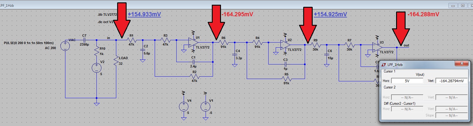
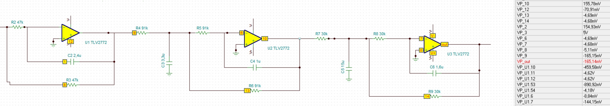
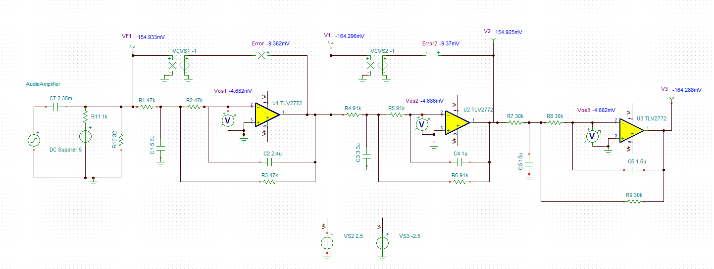
But looks like that is a problem with the SPICE Model, because there is an offset when the voltage is NEGATIVE (output).
This offset is always 9,36mV no matter what is the input (you can change the 32R resistor to other value, and the offset will keep 9,36mV).

Scheme and detailed information is available on the image below:


  • Hi Renato,

    Could you please try to simulate the following schematic in PSpice or TINA-TI as we cannot support our models in LTSpice due to legal issues (LTSpice EULA)?

    Thanks,
    Vivek Agarwal
  • Yes, same problem

    Take a look on the right side.

    There is an offset of 9,36mV between VP_out and VP_10

  • Hi Renato,

    Your post has been transferred to the op amp team and we will assist you to get your circuit working properly. Could you share the TINA schematic file for your design? We'll let you know what we find.
  • Hello,

    The TLV2772 model is a little older and as a result isn't quite as accurate as some of our newer models, but the circuit operation and the behavior looks correct. 

    First, the TLV2772 is a +5V product, which means the maximum voltage between V+ and V- is +5V.  Your simulations show a +/-5V (+10V total) supply setup which will exceed the absolute maximum supply ratings for the TLV2772.

    I modified the supply voltages to +/-2.5V which will work well with the TLV2772.

    The offset voltage for the TLV2772 is modelled to be -4.682mV which is a little larger than I would expect based on the datasheet, but isn't too far off.  The offset of -4.682mV is amplified by the noise gain (non-inverting gain) of the circuits which is 2V/V, resulting in the -9.362mV error on the output of each of the stages.  This is shown below where an ideal G=-1V/V block is created from a voltage-controlled voltage source (VCVS) to compare the actual op amp output to the ideal output based on the input signal. 

  • Hi Collin, thank you for your warm support.

    You wrote which TLV2772 is a little bit older. Can you suggest me anything newer to replace it?

    The purpose is: make a 6th or 8th order low pass filter (1Hz) to be possible read the DC in this circuit.

    As you can see, there is an audio amplifier (AC) and I would like to measure, with accuracy, the DC over R10 (load).

    Have a good day,

    Renato

  • Hi Renato,

    To be clear, I mentioned that the TLV2772 SPICE model is a little older and therefore not as accurate as some of our newer models.  The TLV2772 op amp functions as specified in the product datasheet.

    If you're going to be using +/-5V supplies then you'll need to select a different op amp that can tolerate the larger supply voltage.  Are you using +/-5V supplies or do you intend to use other supply voltages?  Please let us know and we can help you select an appropriate op amp.

  • Hi Collin,

    Thank you for your fast response...

    I have in mind to use a DC/DC Stepdown, like this (it is +5V):

  • The way you have your circuit drawn, your audio input signal will cause a bipolar (+/-) voltage centered around GND. This means that you will run into input/output voltage swing limitations while operating on a single-ended power-supply. You should consider a dual-supply power-supply configuration, such as +/-2.5V or +/-5V to allow for a GND referenced signal chain. Otherwise, you'll need to add a mid-supply ~+2.5V DC offset to your input signal chain.