This thread has been locked.

If you have a related question, please click the "Ask a related question" button in the top right corner. The newly created question will be automatically linked to this question.

TIDA-01418: Change the IGBT to NMOSFET

Part Number: TIDA-01418
Other Parts Discussed in Thread: TIDA-00364, UCC27714, UCC27712, UCC27712-Q1

Dear TI Experts:

I found TIDA-01418 is a nice design example.

I hope to apply it in my targeted application: Vbus=86V (max. Vbus=100V ) and rated 3kW (peak 7KW)  with 3-Shunt FOC control for a 3-Phase PMSM.

Q: Change the IGBT to NMOSFET

I have found the NMOSFET with Vds=150V, Rds=4.8 mOhm, and Id=171A. Could I directly replace the IGBT: IXYP15N65C3D1 module in the inverter with the NMOSFET I found?

Look forward to hearing from you soon.

Best Regards,

Tang Han

  • Dear Tang Han,

    as i understood these are the parameters of your application:

    Vbus = 86 V (100V)

    Prated = 3kW (peak 7kW)

    ==> Irated = 34.8 A (peak 81.3 A)

    Actually you can easily replace IGBT's by using MOSFET's, but please pay attention to the shunt resistors (6x resistors in total, 2 for each phase), they must be adjusted!

    Because of the same power level (like in TIDA-01418) but lower bus voltage in your application, the rated current in your case is pretty high.

    Without adjusting the shunt resistors each time the current (rated) will start to flow the over-current detecting circuit will assume that over current condition has been occurred and will immediately pull down the input/control pins of the gate driver, therefore the power stage (MOSFET half-bridges) will be disabled immediately.

    Best Regards,

    Levan

  • Dear Expert Levan:


    Thanks for your kind and professional reply.
    I will follow your instructions to carefully determine the shunt resistors.  I am sorry that I still have some questions.  

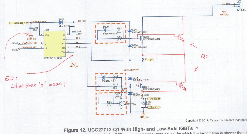
    Q1. For the MOSFET I found (Automotive Qualified, and ID=171A(Tc=25 degree), ID=121A(Tc=100 degree)), do I need to worry about the heat dissipation problem, then apply "Parallel Operation of Power MOSFETs" (mentioned in TIDA-00364).  In the following diagram, I add two MOSFETs to make "two" MOSFETs in parallel. Is the connection right?  Can it work?

    Can UCC27712 drive the following circuit? (It seems that UCC27714 has larger sink/source current, but UCC27714 is not Automotive qualified, so I don't consider it.)

    Q2. In the TIDA-01418 document, I found many 'X' marks, as shown below. Could you kindly tell me what it means?

    Hope to hear from you soon.

    I appreciate your help so much~

    Best Regards,

    Tang Han

  • Dear Tang Han,

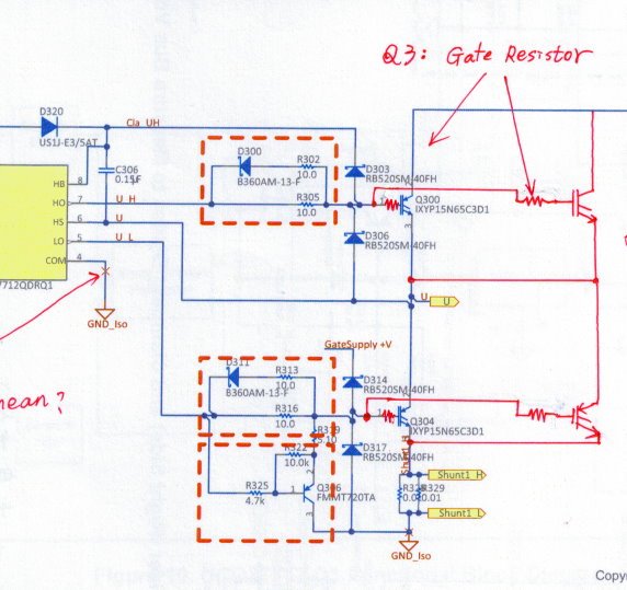
    Q1: Yes. You need to take care about heat dissipation. Paralleling helps to reduce it (RdsOn will be lower). I would suggest you to put at each MOSFET gate its own gate resistor. Every gate path from gate driver to MOSFET should be symmetricall (same resistance, ideally same wire length)

    i think UCC27712-Q1 will be able to drive your circuit, if you face some issues if the sourcing current will not enough you can reduce the value of gate resistors.

    Q2: please ignore it. no meaning.


    Regards,
    Levan
  • Dear Expert Levan:

    Your professional suggestions are really important to TI users.

    Q3: You mentioned the importance of gate resistors, are they those ones I plotted below?  

    I will try to determine the values of the gate resistors. But if you have Intuitive initial values, could you kindly tell me?   ^_^

    Anyway, I am very thankful to you!

    Wish you the best!  Hope to hear from you soon!

    Tang Han

  • Dear Tang Han,

    Q3: Yes, thats right.

    You need to determine those values in your application once you know all the components.

    You can also try to keep the same values and characterize your hardware .

    Regards,

    Levan

  • Dear Expert Levan:
    Thanks for your kind and professional suggestions.
    Wish you the best! 
    Best Regards,
    Tang Han