This thread has been locked.

If you have a related question, please click the "Ask a related question" button in the top right corner. The newly created question will be automatically linked to this question.

TIDA-01471: 8-channel IEPE vibration sensor DAQ

Part Number: TIDA-01471
Other Parts Discussed in Thread: OMAP-L138, , ADS1274, REF6225, REF3425, ADS127L01, ADS8900B, ADS1278, TINA-TI

Dear Ahmed,

I'm planning to implement an IEPE Sensor DAQ with 8-channels based on TIDA-01471 reference design, using and OMAP-L138 processor.

My question is, It's better to implement eight full separate channels or can I use a multiplexer on the input?

I've also reviewed TIDA-010045.

Could you give me any advise?

Thanks in advance!

  • Hello Jorge,

    If your signal bandwidth is 15kHz to 20kHz, then you probably need sampling speed above 64kSPS. note that higher sampling rates would improve the SNR and requires more power and higher speed SPI.

    At this speed, a multiplexed system might be challenging and I believe would degrade the performance expected from the converter and front-end. we are talking here about 18b of ENOBs, not so many multiplexed systems running at higher speed can achieve such high resolution. the high speed amplifiers required to support switching transients would inject a huge amount of noise to the signal path.

    If you are looking at 8 channel implementations, I would suggest the following:

    - use 2 x 4 Ch based on the ADS1274 which is 4 channel simultaneous sampling using the same ADC core. this way you have the benefits of integration (power, and footprint) as well as the benefit of separate channels (higher SNR)

    - if variable gain is not needed, I suggest to drop the variable gain stage to improve SNR. or if really required, then better to use a low noise VGA.

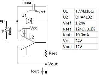
    - I suggest to use a simpler current source instead of the XTR. it can be either fixed current (2 or 4mA), or variable. I'm going to publish an article soon about alternative circuits for high side current source to be used in this circuit. the simple fixed current is shown below.

    -  along with the REF6225 that I have in the TIDA-01471, you can also use the new REF3425

    The 4 channel circuit would look like this:

    /cfs-file/__key/communityserver-discussions-components-files/3370/image004.png

  • The current source would be something like this:

  • Thanks for your prompt response, Ahmed!

    The sensors we plan to use for this project have a frecuency range of 0,4Hz to 15kHz with 100mV/G sensibility. As space it's a constraint, I was thinking in use a common signal conditioning circuitry and secuentially multiplex the input, but I'll take note of your recommendations.

    What about your other reference design, TIDA-010045? Will be possible to use the ADC into OMAP-L128 to sample 8 channels with this input circuitry?

    Thanks!
  • Hello Jorge,

    There is an important thing to note if you are going to use sigma-delta converters (like ADS127L01) in multiplexed architectures: Sigma-delta converters have a digital filter integrated, and it's supposed to be used in continuous conversion and the filter assumes all samples belongs to the same channel. If the converter is used with multiplexed channels, the digital filter has to be flushed out between channels and there will be a latency of multiple cycles in-between. for example if ADS127L01 will be used in multiplexed mode, the maximum sampling frequency would be around 100 kSPS instead of 512 kSPS, this might be sufficient for multiplexing 2 channels only given the BW you mentioned. Moreover, the filter used to attain the shortest latency is not the flat-band filter favored by the IEPE sensor applications, which means further digital processing is required after the ADC.

    The alternative is to use a SAR ADC (like ADS8900B converting 20b @ 1 MSPS) instead, or opt to the simultaneous sampling which I mentioned earlier.

    The TIDA-010045 uses MSP432's internal 14b ADC which, when runs full speed, would achieve about 11b of ENOBs, the TIDA-010045 targets the cost-effective low-performance application. I assume your "DAQ" module would demand higher performance.

    Kind Regards,

  • Dear Ahmed,

    I probably have not explained myself well when I'd said "multiplexed".

    My requirement is to have 8 separate channels for 8 different IEPE vibration sensors. This sensors are going to be readed in a secuential basis. We will sample sensor 1 during 10 seconds, then process the captured data and then move to sensor 2 and so on... so the conversion on each channel will be continuous.

    I've found some comercial products that use only one or two IEPE input channels and then use a second device (a multiplexer) to expand this DAQ to 8 to 16 channels by connecting the output of the multiplexer to the input of one of the channels on the DAQ.

    I'm curious about how they accomplish that as this could be a nice architecture to implement 8-to-1 input board for my project.

    Anyway, I will explore ADS1274 or even ADS1278 as you suggested.

    Regards!

  • Hi Jorge,
    That interleaved-type multiplexing should be fine then, it makes sense then to multiplex if you don't want to have all channels sampled at the same time. the only thing you need to have per channel is a current source and a coupling plus scaling input before the MUX. If the current is switched then it might take seconds to settle, same for the coupling cap HPF which has a very long time constant, but if this is also tolerable then even the current source can be multiplexed.
    Regards!
  • Hi Ahmed,

    Thanks for your support!

    Can you please recommend a multiplexer IC for this task?

    Regards,

  • It seems that MUX is better put after the scaling/HPF as mentioned before, that means we have 3V signal to multiplex. I would say TMUX1108 should be good for 8 channels. but some simulation beforehand is necessary to avoid any surprises. the full TINA-TI circuit model of the signal chain is available on the TIDA-01471 folder.

  • Thanks Ahmed,

    Could I send you the schematics via email when I finish them for your review?

    Regards,
  • Hello Jorge,
    I would prefer not, as we try to avoid any contamination from customer IP. However if there is specific device connection or a small part of the schematic that you want to review and have no issue in putting it public, then I have no problem giving my feedback as well.
    Best Regards,
  • Hi Ahmed,

    May I ask what are the advantages of this current source? is it just simplicity?

    Besides, should I care about the common mode voltage of the current source? because IEPE sensors will need a 24V working voltage.

    Thanks!

    George

  • Hello Goerge,

    The proposed current source is quite simple and possibly sufficient for the application.

    It's not clear to me what is meant by "common-mode voltage of the current source", is it the output DC level? this is set by the load like in IEPE sensor case and should lie within the compliance range of the current source.

    In general the specs for the current source needed for IEPE sensor are:

    - 4mA min current, might be higher according to the cable length or lower for some sensors.

    - 0-22V compliance range (dependent on the sensor DC bias range and output range)

    - 24V min supply

    - ~1uV rms noise (to achieve 17 ENOBs with the given front-end in TIDA-01471)

    - >300kOhm output impedance at 20kHz

    for the IEPE sensor application, absolute accuracy, drift don't play important role in performance as the IEPE sensor output stage DC and gain doesn't depend on the excitation current.

    There are many different topologies that can be used for implementing the current source, one of them is mentioned in this ADJ article.

    Best Regards,

    Ahmed