This thread has been locked.

If you have a related question, please click the "Ask a related question" button in the top right corner. The newly created question will be automatically linked to this question.

PMP4435: Transformer and Inductor Design

Part Number: PMP4435

Dear Sir,

Could you please share the mathcad file for the PMP4435. 

what is the  (Magnetic flux density) Bmax considered for the transformer(T1) design and Output Inductor (L1) design in this full bridge converter. Is the RM6S/ILP core which is used with Ap (area Product): 236 mm4 sufficient for 300W.

Regards,

Nesh

  • Hello Nesh,

    Unfortunately we do not have a Mathcad file and the designer is no longer with us. I will forward your question to the manager of the design team.

    Thanks for your patience,

    Ryan

  • Hi Nesh,
    Same as above mention from Ryan. The designer is no longer here. And he didn’t leave the calculation about this project.
    About your questions…
    1.The "Flux Density"(B) of the "Transformer Core" will related to "Turns of Primary Winding"(Np), "Operated Frequency"(f =1/T), "Working Voltage of Primary Winding"(Vp) and "Effective Flux Area"(Ae).
    In general,
    Formula should be:
    dB = (Vp * dt) / (Np * Ae)
    Parameters:
    Np/Ns1/Ns2 = 6/2/2 (From the specification of transformer)
    Ae= 37.5 mm^ 2 = 37.5 * 10^(-6) m^2
    Vo=12V
    Vp=36V(Vin_min @ D_max=100%, Vo = 12V)
    f = 350K Hz(From the test waveform)
    T= 1 / f = 2.9 uS (First quadrant and Third quadrant)
    dt = T/2 = 1.45 uS (Each quadrant)
    Thus,
    dB = (36 * 1.45u) / ( 6 * 37.5u)= 0.232 Tesla = 2320 Gauss
    Operated Bmax should be 2320 / 2 = 1160 Gauss (Base on balance from each quadrant)
    B_sat = 3800 Gauss@100Degree (Saturation magnetic flux density of specification)
    So,
    dB = 1160 Gauss < 3800 Gauss. It is safe for flux density in transformer.

    2. The "Flux Density"(B) of the "Output Choke" will related to "Turns of Winding"(N), "Maximum Current through the Choke"(Ip) and "Effective Flux Area"(Ae).
    This consideration will be complex in Ferrite Core. Because it will have a Gap in the Flux Loop. Here is no much information on this inductor(L1).
    In general at the first step, we will define the “Output Ripple Current / Output Maximum Current” ratio about 20%. It is also to decide the inductance "L" of “Output Choke” and then, turns of winding.
    We usually base on the "Peak Current"(I_peak), "turns of choke"(N), " to check the "Magnetic Flux Density"(B) in material specification. If using ferrite, we also need to check the gap length of choke. It is trade-off between gap length and number of turns if we keep a target inductance.

    Conclusion of both,
    The Bmax consideration of transformer is Voltage-Second, Np and Ae;
    The Bmax consideration of Inductor is Peak Current, N, Ae and the gap of core.

    3. AP should be good. Because the operation frequency of this project is 350KHz (Higher Frequency) and the PSFB is work in First and Third quadrant(double utilization rate).

    Regards,
    Richard
  • Hi Sir,

    Thanks for the information.

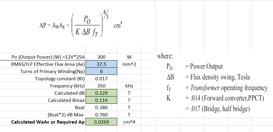
    I have calculated the AP with the B_sat (0.38 Tesla)

    Since PSFB is having double utilization rate, I can keep dB_max as 0.76 Tesla (0.38T x 2) for the AP calculation.

    Is this equation for Ap calculation and the limit for dB_Max correct in case of PSFB.

    Thanks 

    Nesh

  • Hi Nesh,
    Yes. Normally, It is right direction. We will decide the limitation of Ae more carefully. Because we need to keep the margin for some reasons. Unbalance is first consideration, then tolerance from manufacturer…Etc. So maybe you can set the 20% more margin from Bmax limitation.
    AP calculation is more complex from the structure of transformer. Two factors orthogonally from magnetic plane and electronic plane to decide the dimension of structure also the capacity of power. It is definitely a good index for designer that to select a suitable magnetic part.
    Regards,
    Richard
  • Thanks a lot sir for the information.