This thread has been locked.

If you have a related question, please click the "Ask a related question" button in the top right corner. The newly created question will be automatically linked to this question.

TIDA-00778: Anti aliasing filter selecting

Part Number: TIDA-00778

Hello,

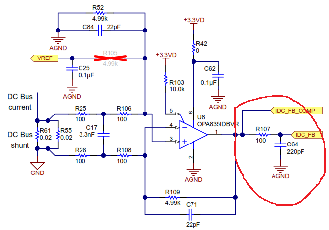
In TIDA-00778 design, we can see a anti aliasing filter with cutoff frequency of 15 MHz. The picture below shows this filter:

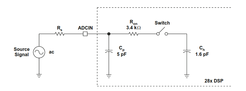
Also, the following  picture shows the ADC input impedance model for TMS32028027F.

So, I have some questions about that:

1-)How do you choose the 15 MHz for cutoff frequency of anti aliasing filter? as far as I know, the cutoff frequency of anti aliasing filter should be smaller than half of sampling frequency and the current sampling frequency in FOC algorithm is 10-20 kHz. so the cutoff frequency of anti aliasing filter should be smaller than 5-10khz.

2-)How do you calculate the 15 MHz?

3-)When we need this filter?

Regards,

Mohammad.

  • Hi Mohammed,

    Thanks for reaching out. I am adding my comments to your questions one by one below.

    1. The concept of choosing half the  frequency cannot be applied on the inverter switching frequency. With 20 kHz PWM, if we select a filter with 10 kHz it will filter out all the switching current information. Here I want to measure the current information in every switching cycle very accurately. In other way I want the exact switching current to be available at the amplifier output. So cut off frequency should be sufficiently higher than the switching frequency (here 20 kHz), to eliminate the error due to filter.

    2. How to select this filter? - One of the objective of designing this amplifier circuit is to sense the current through the shunt when the IGBT switches. So we need fast settling (less than 1us is the target value in the design). If the filter is large, it will introduce delay and increases the settling time. The filter is selected to eliminate coupled noise coming from the IGBT switching, voltage oscillation across the shunt resistor (due to the inductance of shunt) etc. This noise frequency is of the order of 20-50MHz depending on how fast we are switching the IGBTs. I have selected a minimum value filter to eliminate the high frequency noise (20-50MHz), which will ensure that the filter delay is minimum as well as the high freqnecy noises are filtered. The filter capacitor value C64 (220pF) is selected sufficiently higher than the sampling capacitor (Cp) of the MCU, ideally more than 20 times.

    Please refer section 1.1.1 of the TIDA-00778 design document http://www.ti.com/lit/ug/tiducy7/tiducy7.pdf for detailed explanation on switching current sampling, sensing delays, and on why we need faster response.

    3. Answered in point 2.

    Hope this clarifies.

    Thanks & regards,

    Manu

  • Thanks for your response,That resolved my issue.

    I have another question, I tried the f=1/2/pi/r/c for calculation of cutoff frequency: 1/2/pi/100/(220+5)=7 .07 MHz.
    But in TIDA-00778 has been mentioned that :f= 15 MHz , so what is my mistake?

    Regards,

    Mohammad.
  • Hi Mohammed,

    Your calculation is correct. It looks like 15Mhz is a typo in the document. I will correct this. Thanks for pointing out.

    Thanks & Regards,

    Manu