This thread has been locked.

If you have a related question, please click the "Ask a related question" button in the top right corner. The newly created question will be automatically linked to this question.

TINA/Spice/TPS40210: TINA simulation problem

Part Number: TPS40210
Other Parts Discussed in Thread: TINA-TI,

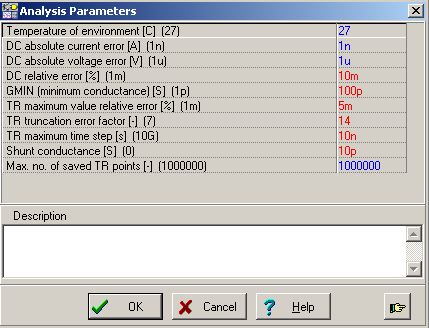
Tool/software: TINA-TI or Spice Models

Hello,

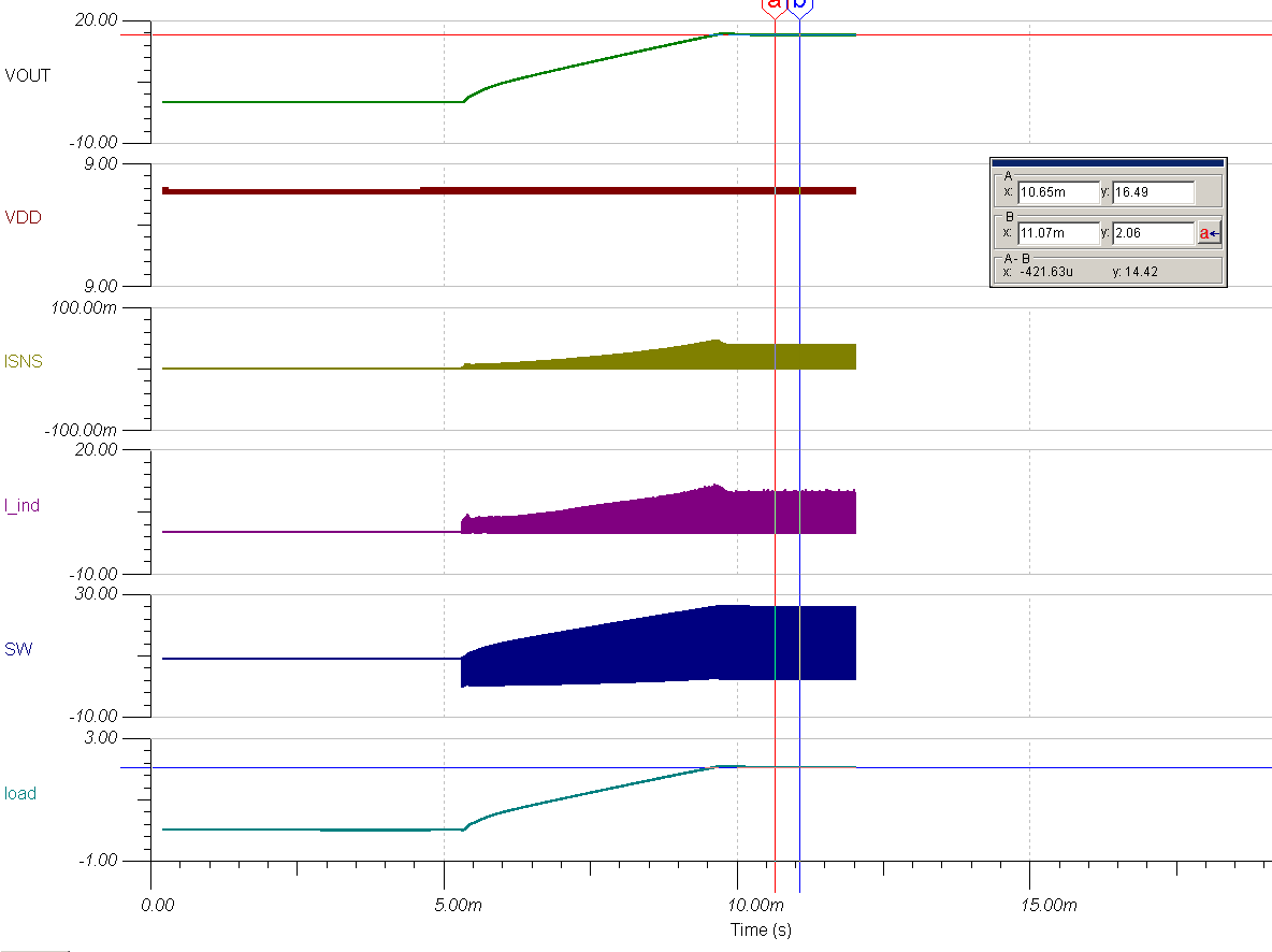
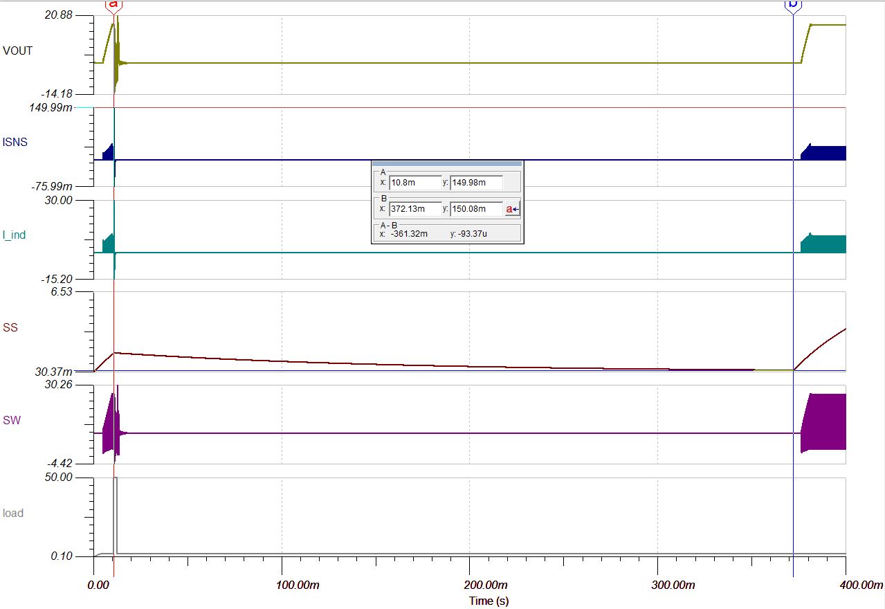
I have a simulation problem with TPS40210. The circuit didnt work correctly.

I checked my design also with webench but i use similar transistor and diode in the simulation.

My spec. is 8-35Vdcinput, 16.5Vdc output and maximum load is 1.7A.

You can find the tsc file in the attachment.

Could you please give an advice about the simulation?

Best Regards,

sepic_transient.TSC

  • Hi,

    FYI, one of our team will take a look at this.

    Herman
  • Hi Herman,

    Maximum ambient temperature is 85°C. FYI.
  • Hi Bulent,

    Please use the Sepic reference design available in product folder.

    TPS40210 TINA-TI SEPIC Reference Design (Rev. A)

    It uses latest Pspice model but the one you attached above uses old model.

    I configured your setup on this Sepic reference design and it is working as expected. PFA tsc file and simulation results.

    slum492a_04JUN.tsc

  • Thanks for your response.
    How can i add 85°C ambient temperature to simulation?
  • Hi Bulent,

    Temperature effects are not modeled for this device. So, you will not observe variation across temperatures.

    If you want to add temperature then  you can change Temperature of environment in "Set Analysis Parameter" option.

  • Hi again,

    When i apply a short circuit to the output side just for 2msec, the output goes to 0V as expected but it doesnt come to correct value when the short circuit problem is gone.

    Also, i simulated this circuit in LTSpice. After the short circuit condition, output doesnt recovery and stucks to 0V.

    Another question: The behavior of the same circuit is very different with LTSpice and TINA. Is it normal?

    Regards,

    Bulent

  • Hi Bulent,

    I will check this behavior in TINA-TI and will get back to you.

    Please note that we do not support our model in LTSpice and will not able to comment on any difference in behavior observed between TINA-TI and LTSpice.

  • Hello again,


    I implemented the sepic controller design.

      • Load 16V5DC with 1A at 14V input. Eff = 88.5%, during 3 hours. It is ok.
      • Load 16V5DC with 1A at 8V input. Eff = 88%, during 2 hours. It is ok.
      • Load 16V5DC with 1A at 18V input. It is ok.
      • Apply a short circuit to the output. It closed the output and when fault condition is cleaned, it turn-on again the output. It is ok.
    • although efficiency at 14V input is better than 8V input. But, at 14V input case, there is more thermal dissipation especially in the inductor. I checked the PWM signal, it was ok.

     Could you please share your opinion about the inductor temperature?

    14V 1.586A input, Load 16.39V 1A Eff = 88.5%

    TPS40210

    Time (min)

    Inductor (°C)

    Thermal Camera

    SW + Diode (°C)

    Thermal Camera

    Resolver cct (°C)

    Thermal Camera

    35

    72.8

    60.2

    49.4

    40

    73.0

    59.8

    49.9

    45

    74.0

    60.4

    50.1

    50

    73.1

    60.6

    50.1

    55

    73.2

    60.5

    50.2

    60

    72.8

    60.3

    49.7

    65

    72.9

    60.3

    49.8

    70

    74.2

    60.7

    50.1

    75

    73.6

    60.8

    49.9


    8V 2.752A input, Load 16.39V 1A without load input current 0.426A, eff = 88%

    TPS40210

    Time (min)

    Inductor (°C)

    Thermal Camera

    SW + Diode (°C)

    Thermal Camera

    Resolver cct (°C)

    Thermal Camera

    1

    35.4

    42.8

    40.4

    5

    55.3

    53.2

    48.4

    10

    62.4

    58.9

    49.6

    15

    64.2

    60.2

    50.2

    20

    64.7

    60.1

    50.6

    25

    65.4

    60.7

    50.2

    30

    65.4

    59.5

    50.4

    35

    65.2

    60.3

    50.8

    40

    65.2

    60.1

    50.8

    45

    65.4

    60.9

    50.6

    50

    65.4

    61.2

    50.8

    55

    65.1

    60.1

    50.8

    60

    65.3

    60.9

    50.8


    Regards,

  • I think the increased dissipation in the inductor is due to differences in core losses at the two input voltages.  The V*second product is slightly lower for the inductor when running at 8V than it is when running at 14V.  My quick BOE calculation says that the converter is running at approximately 67% duty-cycle at 8V in and 54% at 14V input.  Assuming a 250KHz switching frequency that yields a switch "On" time of 2.68µs @ 8V and 2.16µS @ 14V.  Calculating the V*s products shows that @ 14V the inductor sees 30.2 µV*s compared with the 21.4 µV*s at 8V each cycle.  The larger V*s product at 14V results in a larger flux change in the inductor core which manifests as increased dissipation in the core and an increase in temperature.  The exact difference in core losses will depend upon the material used for the inductor core but the formula for core loss varies as an exponential function of flux change.  The exact exponent is material specific but we can assume that the 50% increase in flux swing could potentially lead to over a 2x increase in core dissipation.  https://www.mag-inc.com/Design/Design-Guides/Powder-Core-Loss-Calculation

    There is a difference in the I2R winding losses between the two conditions that skews losses higher the lower you go in voltage, but assuming the winding resistance is on the order of 100 mΩ the increased winding losses due to higher currents is likely small compared to the increase in core losses.

    Shawn

  • Thanks for your response. So do you suggest to change the inductor?

  • I am looking forward to your reply asap about reducing the temperature of the inductor

  • Hi Bulent,

    I have configured your setup to test the short circuit condition by applying high current for 2msec and it is working as expected. PFA tsc file and simulation results.

    7343.slum492a_04JUN.TSC


    As per the datasheet, the device stops switching when voltage at ISNS goes above 150mV (Overcurrent detection threshold at ISNS pin=150mV). The device restarts after the SS pin discharges to the soft-start reset threshold, VSS(rst)=150mV.

    In the test setup Css=100nF and Rss(dis)=1500Kohm(internal to the model). So the time taken for the device to restart after the short circuit event is ~385ms.

    Regards,

    Yashmitha