This thread has been locked.

If you have a related question, please click the "Ask a related question" button in the top right corner. The newly created question will be automatically linked to this question.

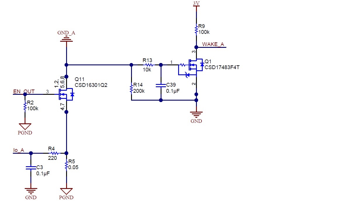
PMP4451: circuit diagram & firmware define

Part Number: PMP4451

Dear TI-er.

My customer want explain circuit diagram & firmware define.

plz help me.

    #define CURRENT_A_LOAD_ATTACH_THRESHOLD  2
    #define CURRENT_A_LOAD_FULL_THRESHOLD       2
    #define CURRENT_A_OVER_LOAD_THRESHOLD  44
    #define CURRENT_A_TYPEC_HALF_THRESHOLD     22
  • Hi Kiyong,

    We are looking into this questions and will be back to you soon.

    Thanks,

    Robert

  • Hi, Kiyong,

    This circuit diagram is designed for whether there is the device on port A. The logic is: MCU will send the EN_OUT signal(high level) periodically and use the ADC to read the Io_A value. In the firmware, there is the load attach, over load macro define for port A. The value of  Io_A will be compared with defined value.

    1.  When the value of  Io_A is above load attach value, the netGND_A of port A will connect with PGND through turning on Q11 and R5.

    2.  When the value of  Io_A is above over load value, the net GND_A of port A will disconnect with PGND through turning off Q11.

    Thanks!