This thread has been locked.

If you have a related question, please click the "Ask a related question" button in the top right corner. The newly created question will be automatically linked to this question.

Passive first order high-pass filter transient response to .wav

Hi,

I simulated a simple first order high-pass filter using a .wav file as input, but the transient response doesn't follow input signal. The circuit I use is the following:High-pass.TSC

And the .wav file is:

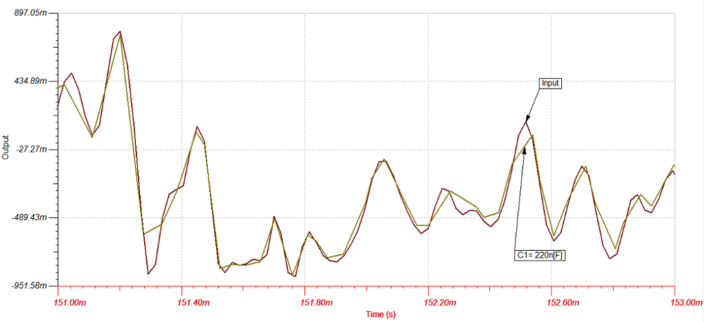
I simulated with Capacitor value of 1uF and 4,7uF and the transient response between 151ms and 153ms is quite strange...

What is the issue?

Many thanks.

  • Hello Luigi,
    Thank you for posting to E2E.

    I used the WAV file as stimulus for VG1, However I had to change the Amp meter settings from OUTPUT to none.
    Otherwise there was no output to VF1


    I see nothing strange 100ms-200ms into the waveform.
    Below is the VG1 (wav stimulus) and VF1 output of the  high pass.
    The VF1 appears to match the VG1 input.

  • Hi Ed,

    thank you for your quick answer.

    What I found strange is the following:

    The .wav signal seems strange too: it's a PCM 16 bit with 44,1 Khz sample rate, but the signal shape seems not to use the 22,6us sampled pionts. And the output of the HP filter doesn't follow the input signal.

    Best regards,

    Luigi

  • Hello Luigi,

    What you are seeing here is similar to what happens with an A-D converter.
    The software can only look at so many samples in time.
    The resolution suffers when you increase the time span, The sample time is too infrequent.

    I changed the Transient window, reran the WAV file, and overlayed the results.
    They match.

    And here is the TINA file I am using, yours modified.

    /cfs-file/__key/communityserver-discussions-components-files/234/High_2D00_pass-_2800_3_2900_.TSC

  • Hello Ed,

    thx!

    How many samples in time are managed by the software?

    With a 44,1 Khz sampling rate, each point is every 22,67us, therefore in a 2ms time window there should be 88 samples.

    How have you changed the transient window? I see a 2ms window...

    Anyway, I run the transient with the circuit you sent me and the input and output curve have some mismatch between 4 and 6ms and between 8 and 10ms.

    Which analysis parameter I have to set to get the smoothest curve?

    Luigi

  • Hi Luigi,

    I think what you are seeing is correct. The last image you posted is with a lower C1 value than ED used so the High Pass Filter pole frequency is higher. This means that for low frequency components of the .wav input, phase shift and attenuation is introduced in the output. This distorts the output waveform at those frequencies causing the input vs output differences you see. As far as the input not being "smooth" and sinusoidal, that's because it is a sample generated signal with many varying amplitude, phase shifted frequency components. If you did a Fourier analysis of the input you would see that. For your single pole high pass filter circuit, the best way to get the input (voltage) to match the output is to increase the C1 value as much as possible and/or increase the load resistor value. This will move the high pass filter pole lower which minimizes the distortion introduced in the output due to the filter attenuation and phase shift for low frequency components of the input signal.