This thread has been locked.

If you have a related question, please click the "Ask a related question" button in the top right corner. The newly created question will be automatically linked to this question.

WEBENCH® Tools/TPS63050: WEBENCH Power Designer: Inaccurate part suggestions and incorrect macros!

Part Number: TPS63050
Other Parts Discussed in Thread: TINA-TI

Tool/software: WEBENCH® Design Tools

Hello there!

I designed a boost converter using TPS63050 on the WEBENCH Power Designer for generating a 5V/0.5A supply from a single-cell Li-Ion/Li-Po battery. The WEBENCH Power Designer completed the recommended circuitry as well as provided suggestions based on the specifications I provided. And that's a really nice thing about it. However, there seems to be a little catch in this.

The circuit is as follows:

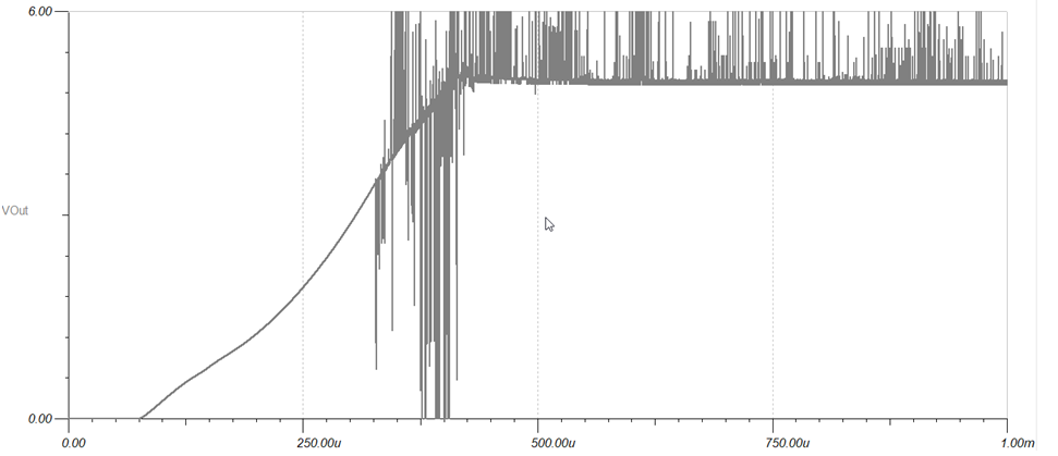
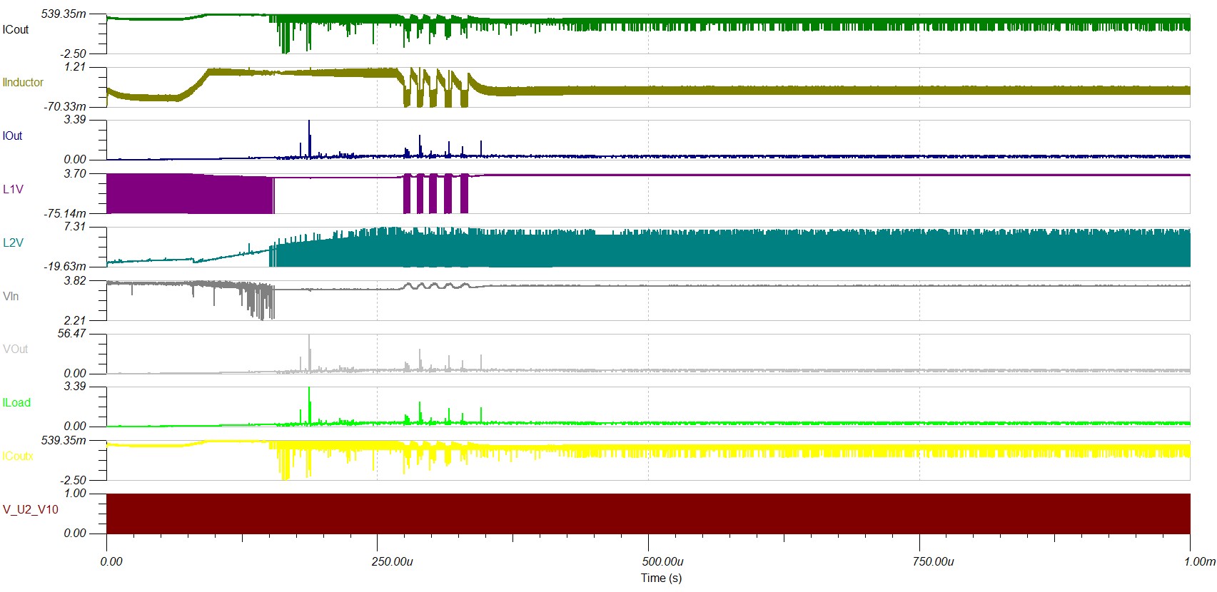
I exported the file and run transient simulation in TINA-TI, and this is the response I received:

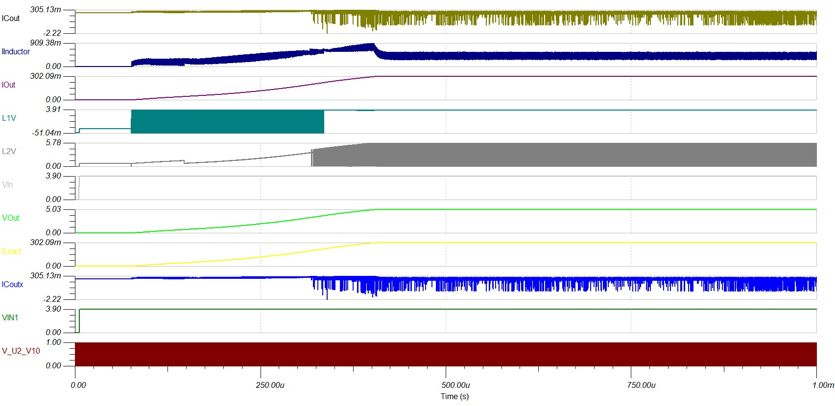
Please note the Vout stable at 5V and Iout stable at 300mA.

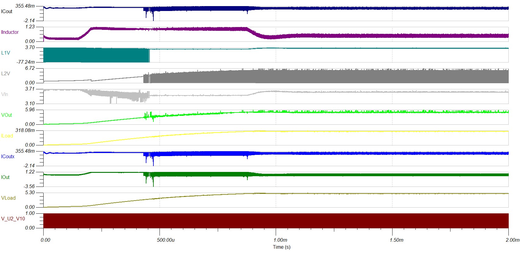
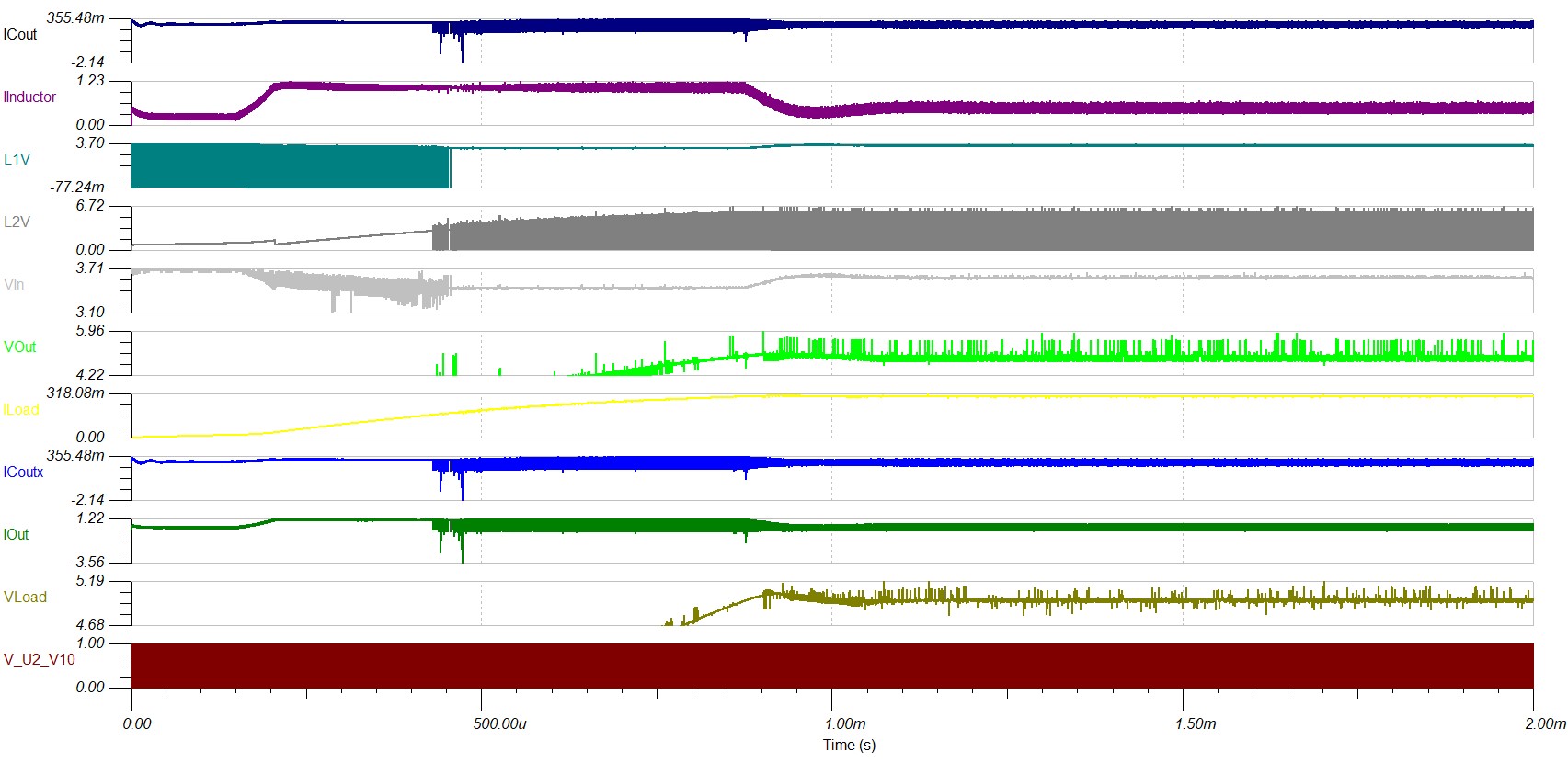
When I started checking the individual components, I found out that the spice file provided by the manufacturer of Cout and Coutx (both are the same in this application, Part No.: EMK107BBJ106MA-T, Manufacturer: Taiyo Yuden) and the one included in the original file exported from WEBENCH Power Designer were not the same. When I replaced both these capacitors in the original file by the spice macros I downloaded from the original manufacturer, this is what TINA-TI is giving:

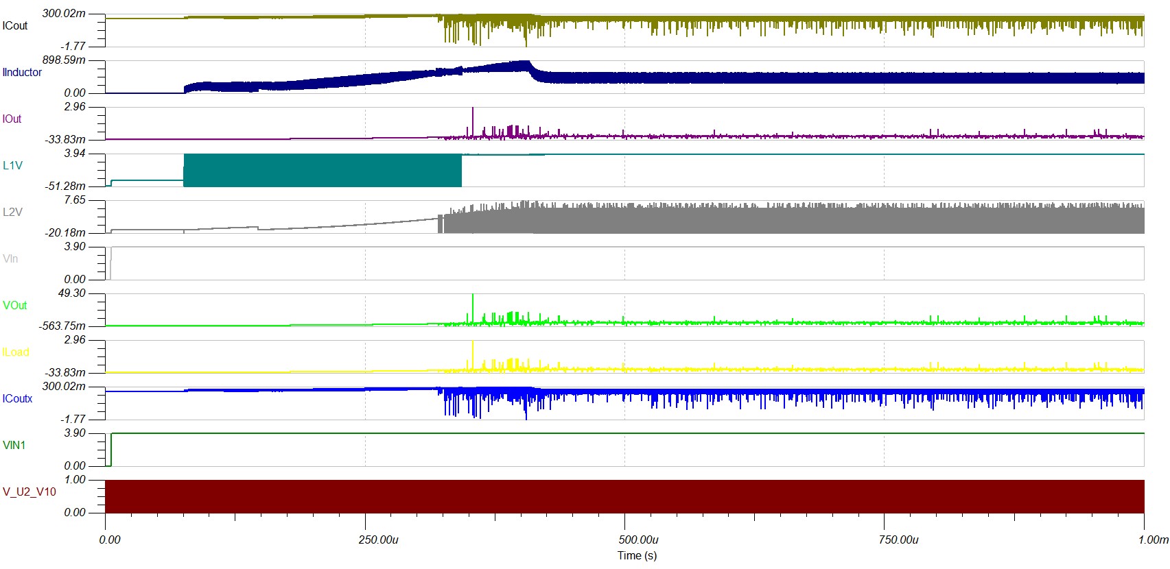
Please note the highly unstable nature of all the node voltages and currents.

It seems the system went into instability!

This has created an ambiguity capable enough to shake my trusts in WEBENCH tools and the content they provide!

Could anyone please from the TI family please come forward to help me understand how there exists such a big difference in the design files of the same device (as small as a capacitor) provided by the original manufacturer and provided by the WEBENCH tools.

Also, it would be really helpful if anyone could guide me towards how to bring the system back into stability.

Please find both the simulation files attached herewith.

Looking forward to hearing back soon.

Warm regards,

Abbas Mehdi.

OriginalCircuit.TSC

ModifiedCircuit.TSC

  • Hi Abbas Mehdi,

    We use generic template based SPICE models for Passive components (Capacitors, Inductors) and Switches (MOSFETs, Diodes). While the key low frequency characteristics like dc bias derating for Cap,  Rdson for FET etc are included in the model, the high frequency behavior like ESL value is not very accurate in WEBENCH models.

    The vendor model ( Taiyo Yuden in the above case) is probably more accurate. Note that the vendor model is provided for DC bias = 0 and you will need to update the capacitance value to match with the derated capacitor value when you use the vendor model.

    To capture high frequency effects like accurate noise on output and input node or ringing behavior on switch node - we recommend you download the vendor SPICE models and perform simulations on offline tools like OrCad / TINA-TI. You should also validate on bench as the high frequency effects are often difficult to model and may also depend on the layout or other factors. 

    To add, the analysis parameters also play vital role in simulation. If you set them too loose, you observe such glitches in graph. you can observe the vout settling to 5V in your modified simulations if you set the Y axis between 0V and 6V. the glitches are present because the simulator is not able to converge at those points due to very loose analysis parameters.

    Regards,

    Vishwanath

  • Thanks for the response, Vishwanath. Really appreciate it.

    you will need to update the capacitance value to match with the derated capacitor value when you use the vendor model.

    Thanks a lot for pointing that out. Could you please guide me to some tutorial or something for me to understand and adjust the model for the aforementioned details?

    To add, the analysis parameters also play vital role in simulation. If you set them too loose, you observe such glitches in graph.

    Could you please specify which analysis parameters are you mentioning here?

    I am pretty new to spice. Although I have watched the entire tutorial for Getting started with TINA-TI, but that's all it was, just an introduction. Could you please guide me to a tutorial or similar resource explaining the details of these simulation parameters? It would be really appreciable.

    you can observe the vout settling to 5V in your modified simulations if you set the Y axis between 0V and 6V.

    Yes, but I can also see that the vout spikes as high as 49V, which could be devastating for any device of that scale. My concern here is whether the glitches and the spikes are due to correct simulation, or due to incorrect simulation!

    the glitches are present because the simulator is not able to converge at those points due to very loose analysis parameters.

    You are suggesting here that the spikes are due to incorrect simualtion, and nothing of that sort would happen in the real, physical implementation of the system, right?

    Again, I would like to request if anyone could guide me to any tutorial or technical resources detialing on these parameters?

    Looking forward to hearing back soon.

    Warm regards,

    Abbas Mehdi.

  • Hi Abbas Mehdi,

    1. In case of ceramic capacitors, rated capacitance or the capacitor face value is the capacitance at 0V DC. as you increase the voltage across the terminals the capacitance reduces. This phenomenon is called Derating. there is no direct mathematical equation to calculate the derated capacitance. generally manufacturer gives a detailed graph of Capacitance Vs voltage in datasheet.

    2. In case of simulation parameters, in your TINA tool, go to Analysis and click on set parameters. Since you're performing transient simulation 2 things are important. DC operating point calculation and Transient calculations. I'd recommend you explore these further as there are too many to explain in this forum.

    3. Regarding the spikes in graph, Although we suspect them to be simulation glitches, you should verify the on board results before proceeding further. simulations use lot of approximations and are not proof of silicon results.

    4. You can look for spice Transient simulation analysis parameters on the internet, there are several sources available online. I would recommend to try tuning your time step and DC tolerance parameters and try simulating to begin with. this is an iterative process. there is no formula to calculate these analysis parameters either.

    Regards,

    Vishwanath

  • Hello Vishwanath.

    I tried a lot of different settings, even tried replacing the passives with various alternatives, but this is the best I could get.

    Please find attached the circuit with the selected alternative parts that yield the above result.

    It would be really appreciable if someone could help me in settling down the output of this circuit.

    Looking forward to hearing back soon.

    Warm regards,

    Abbas Mehdi.

    8304.Boost.TSC

  • Hi Abbas,

    The ringing is mainly due to High ESL(equivalent series inductance) of the Cout you have used. A quick fix to your problem would be to select an alternate Cout with low ESL. Please note that ESL is a very high frequency effect and is generally a trait of electrolytic capacitors.

    However, if you want us to modify the analysis parameters and give it a try, please share the webench design from which you exported the simulations. once you log in to webench power designer, you can find it under my designs.

    Regards,

    Vishwanath

  • Hello Vishwanath.

    A quick fix to your problem would be to select an alternate Cout with low ESL.

    I tried dozens of alternatives, but none yields a better result.

    Please note that ESL is a very high frequency effect and is generally a trait of electrolytic capacitors.

    I would like to mention here that all the capacitors being used in the design are ceramic.


    Moreover, I found this article detailing on SPICE convergence. Although it is not focussed on TINA-TI, a lot of suggestions and recommendations are common to almost all SPICE. This helped in signifiantly reducing the glitches.


    For my specific case, setting the RELTOL to 0.01% instead of the default 0.001% did the trick. The output is a lot stable now.

  • Hi Abbas,

    Ceramic capacitors have negligible ESL. We generally ignore it for the frequency range we operate in the order of few hundred kHz. If you were able to resolve the simulation glitches, I'll be closing this thread. Please share the design or write back to us if you have any further queries.

    Regards,

    Vishwanath

  • Although the glitches and spikes have greatly reduced, they are still present in such a fashion that I highly doubt that these are the actual electronic disturbances!

    Looking at the nature of these spikes, I am very much that these are due to simulation errors.

    I tried everything I could to eliminate these simulation errors, but couldn't get rid of them! Even added an LC filter at the output, but the sharp glitches are still present, which give me more confidence in concluding that these are simulation errors.

    The original WEBENCH design could be found here.

    And here is the modified TINA-TI simulation file that yields the best results: 3301.boost.TSC

    It would be really appreciable if the TI team could look into the affair and help me in getting rid of the simulation errors causing these sharp spikes.

    Looking forward to hearing back soon.

    Warm regards,

    Abbas Mehdi.

  • This seems to be common trend for WEBENCH designs exported into TINA-TI.

    I designed a buck converter around TPS62801YKA, exported the design into TINA-TI, and ran the transient analysis. Everything was perfectly smooth.

    As soon as I replaced the output capacitor with the manufacturer's macro, it yielded the same glitchy, spiky output as with the TPS63050 boost converter discussed above. Here are the output waveforms:

    Requesting the TI team to look into the affair, and help me get this cleared soon.

    Warm regards,

    Abbas Mehdi.

  • Hi Abbas,

    The issue of spikes/high frequency noise you see in Vout may be due to ESL of the capacitor  or simulator accuracy issues as already pointed out by Vishwanath above.

    You will observe exactly the same spikes irrespective of whether the schematic is imported from WEBENCH or created from scratch by downloading the SPICE model from TI and creating the schematic - as long as you use the same capacitor model. This is not the property of TI IC  spice model or WEBENCH - but the property of the vendor Cout spice model. Default exports from WEBENCH use generic SPICE model for passives and the ESL in the generic SPICE model is very low - so you do not observe these spikes. We cannot comment on the accuracy of the specific vendor SPICE model you are using. 

    I encourage you to select low ESL output caps - if the ESL is large, please use an additional smaller parallel cap with low ESL. As an example - I included a 1uF ideal cap in parallel to your modified schematic with vendor models and the results look good.

    We also encourage you to test the system on bench as high frequency noise is typically not accurately captured in the spice models.

    If you continue to face issues - please consider below for help

    1. Support forum for TINA (http://www.tina.com/) to help with convergence / other simulation parameters.

    2. Support forum for corresponding passive SPICE model supplier to confirm the model accuracy and on the process to apply voltage derating to the Cap model.

    As the issue is not related to WEBENCH - we will close this post. Thank you for using WEBENCH and hope you can get your simulation / passive spice model issue resolved with above pointers. 

    Best Regards,

    Srikanth Pam

    Online Design Tools

  • Hello Srikanth.

    Thank you for responding to this thread.

    As I mentioned in the previous posts in this thread, the capacitors used in the design are all SMD MLCC, which inherently have negligible ESL. Also, as I mentioned earlier, the spikes and glitches persist, irrespective of which MLCC I use, from whichever manufacturer!

    I have even tried contacting the TINA guys, but it seems the problem is not with TINA either.

    I am still working on it, as I need to resolve this as soon as possible.

    Warm regards,

    Abbas Mehdi.

  • The Designsoft guys confirmed the cause of the problem are the models. Please find the snapshot of communications with the Designsoft people attached herewith.

    Requesting the TI people to update the simulation models, hoping that they would do their best in preventing such problems to occur in future models.

    TI People: It really consumes a lot of time of your customers!

    Warm regards,

    Abbas Mehdi.

    designsoft.pdf