This thread has been locked.

If you have a related question, please click the "Ask a related question" button in the top right corner. The newly created question will be automatically linked to this question.

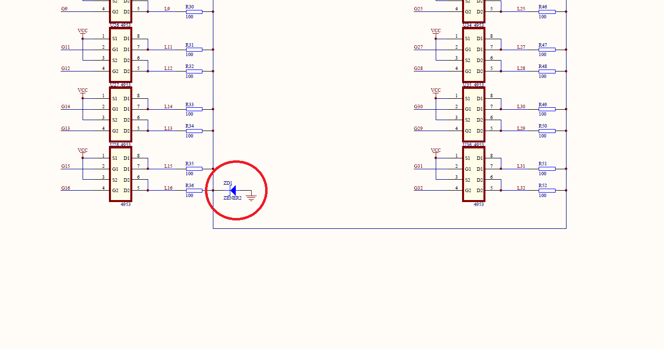
TIDA-00161: The purpose of the Zener diode on the schematic

Expert 6310 points
Part Number: TIDA-00161

Hello,

the below marked Zener is BZV55-C3V0 (according to TIDA-00161 BOM), has 3V working voltage, whereas the nominal voltage of the used RGB LEDs (HT-B3053FCH) can be up to 3.8V.

In this case the RGB (in fact the G and B) would not be properly driven with the sufficient voltage - is that correct, or are we missing something?

From a different post I saw the explanation that the Zener diode is there to prevent (clamp) excess voltage stress across the LEDs, though why would this particular type (with 3V) be chosen here then?

Thanks for the explanation.

  • Hi, Bart,

    there are resistors connected between the line switches and Zener. when the line is not selected, the Zener diode helps the un-selected lines voltage no higher than 3V, which can prevent the ghosting phenomenon.

    Regards,

    Shawn

  • Hi Shawn,

    thanks for the feedback. At first it sounds logical, but we'd like to double check one thing - let's say with L1 row being driven, the Zener is supposed to protect the remaining L2-L32 rows from ghosting, though the voltage visible on it of 3V (BZV55-C3V0) can cause the red diodes of the RGBs used in the project to light up (those are HT-B3053FCH-E7 that have typical VF=2V for red diode - page 8 of its datasheet). 

    So shouldn't the Zener be lower than VF of the diode, so for instance 1.8V, to make sure that ghosting is eliminated?

    Thanks for clarifying.

  • Hi Bart,

    the output voltage of red Channel is VLED-VfR, rather than 0V, so when L1 row is driven, keep the L2/L3 voltage smaller than L1 with some margin, the LED on L2/L3 won't light.

    Meanwhile, 1.8V is also OK.

    Regards,

    Shawn