This thread has been locked.

If you have a related question, please click the "Ask a related question" button in the top right corner. The newly created question will be automatically linked to this question.

WEBENCH® Tools/TPS40170: Temperature testing failure

Part Number: TPS40170
Other Parts Discussed in Thread: CSD18504Q5A, CSD18537NQ5A,

Tool/software: WEBENCH® Design Tools

Good Morning,

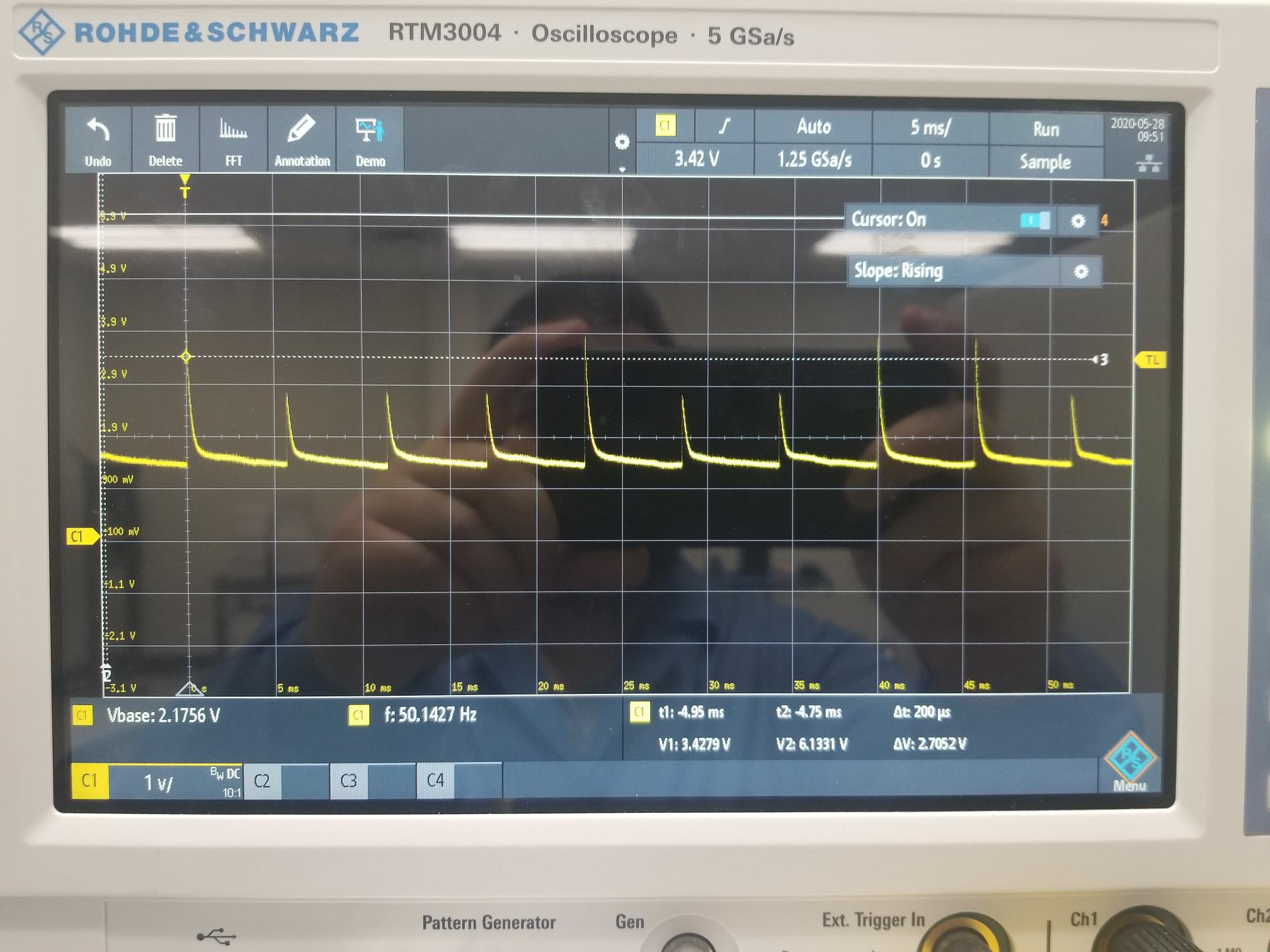
We designed a system that utilizes the TPS40170. We used WEBENCH to design the system to set the voltage at approximately 6V and with a current limit of 6 amps with an input range of 6.9V to 25V. The design was originally created back in 2016. At room temperature the circuit works as expected but as the temperature is dropped towards -20C the circuit begins to fail. We normally set the input voltage to 12V but I noticed that as the system gets colder and fails, if I increase the input voltage the system will begin to work again. All components are rated for -40C. The failure that I'm seeing shows the output voltage spiking and then falling quickly before reaching 6V (typically just under 3V, it then appears to repeat itself after approximately 5ms. We were trying to possibly adjust current limits to see if that resolved the problem but we cannot recreate the design we have in WEBENCH due to the MOSFETs being unavailable as substitute parts any longer (CSD18504Q5A and CSD18537NQ5A). I tried to use the equation for calculating R_ILIM in the datasheet but I cannot recreate the calculated value provided by WEBENCH. Any help in these series of problems will be greatly appreciated.

Thank you,

Brian

  • Hi Brian,

    Could you please share the design that you used from webench Or parameters (Vin, Vout Iout TA) for which the design was created? we will definitely do all we can resolve your issue.

    Regards,

    Vishwanath

  • HI Brian,

    Thanks for sharing the design. We will look into it and get back to you asap

    Regards,

    Vishwanath

  • Hello Vishwanath,

    Please excuse the poor image, but I have provided the V_out of the circuit in question. This is taken at -20C with an input voltage of 12V. I no longer believe that this may be an over-current condition (even though I'd still like to understand how WEBENCH calculates R_ILIM) based off of some testing at room temperature where I caused an over-current condition and the V_out waveform seems very different. Have you heard of any resonant issues that could cause this type of output? I will say that if this condition occurs under the described input conditions, I can increase the voltage to about 17.7V and V_out will drive to it's normal output of 6V. At that time where the output is nominal I can then decrease the input voltage back to 12V (or lower) and the supply output remains steadily on. If you were to then quickly power down the input to 0V and then back up 12V you would see V_out as the attached image. This makes me believe that there isn't a self heating element to this problem even though it does seem related to a startup condition.

    Respectfully,

    Brian

  • Hello Vishwanath,

    I wanted to follow up with some further information that might assist you and your team with this one. I did some load testing at room temperature. With the input voltage set to 12V, if there is a 700mA or greater load at Vout then I will receive a failure similar to the above image. If I then increase the voltage slightly to approximately 14V V_out settles to a nominal level and the system seems fine as described before when this happens during a fault condition. Something interesting is that if I decrease the input voltage to 9V I don't receive a failure like this unless I try to pull closer to 4.5A. All of these conditions had the load demanding on startup of the supply. This changed the outcome from the same loads applied once the system was already powered on which contrasts compared to how the testing was done on my last post here. All of the initial failures indicated at -20C would be similar to my most recent testing in that the demand would be present at the supply when the supply first receives input voltage/enable.

    I have replaced the R_ILIM resistor on one unit to a 60k (from 22.6K) resistor as well as R_comp2 was replaced with a 330ohm (from 1.43K) resistor. On that unit I did not see the same failures at room temperature or at -20C, everything performed nominally. I cannot explain why this would affect the system as described.

    Thank you,

    Brian

  • Hi Brian,

    From webench side, we are not able to test a board/design for ambient temperate temperature variations along with BOM changes and arrive at a conclusion. I'll move this to thread to the experts. 

    Regards,

    Vishwanath

  • Hi,

    Could you please upload your schematic and BOM? Also, please help probe SW voltage and inductor current together with output voltage, these will help a better look into this issue, thanks.

  • Hi Iven,

    I have to spend some time separating the applicable BOM items since I can't turn over the entire BOM for the system. I can say that everything is rated to at least -40C. To hopefully enable parallel work I'll provide the latest information that I have from testing. I can't measure all of the current through the inductor due to the footprint of the inductor, but I can provide the majority that passes through the inductor to the load (this has been the measurement any time I referenced a load value on the system thus far). I will work to monitor SW voltage during these failed conditions to provide more information when I can later on today. I have attached the section of the schematic related to the system in question.

    With that said I had a test setup similar to my last setup except I ran it in the temperature chamber. With the chamber approaching -20C I would set a load, and then power on the system. Similar behavior to before was evident with degraded values as temperature dropped. Ultimately when the unit was cooled and soaked at -20C for ten minutes I could only get a proper steady state voltage output (and power good) if the load current was less than 30mA with an input voltage of 12V. Behavior once powered on remained the same as described before where the load can be increased once steady state is achieved and the steady state does not fall out under nominal load conditions designed.

    Thank you for your help I'll be sure to follow up with the missing information you asked for.

    -Brian

  • I've attached the BOM for the above schematic 6V_BOM.xlsx

  • Hi,

    Could you please also help probe SW voltage and inductor current together with output voltage in the failure conditions? Thanks.