This thread has been locked.

If you have a related question, please click the "Ask a related question" button in the top right corner. The newly created question will be automatically linked to this question.

TIDA-01604: TIDA-01604 Zero-Crossing Spike

Part Number: TIDA-01604
Other Parts Discussed in Thread: POWERSUITE

Dear Manish,

Hello,

I made a totem-pole PFC based on TIDA-01604.

My converter consists of one phase, not 3-phase(TIDA-01604). but I used the same component(four SiC Switch). It also is controlled by 28379D.

Input Voltage : 220VRMS

Output Voltage: 400VDC

Switching Frequency: 100kHz

Inductance: 500uH

Power Factor in the experiment: almost 0.99

Power: almost 400[w]

According to TI Design GUIDE, I completed the overall build level and so my converter is working on Build Level 3.
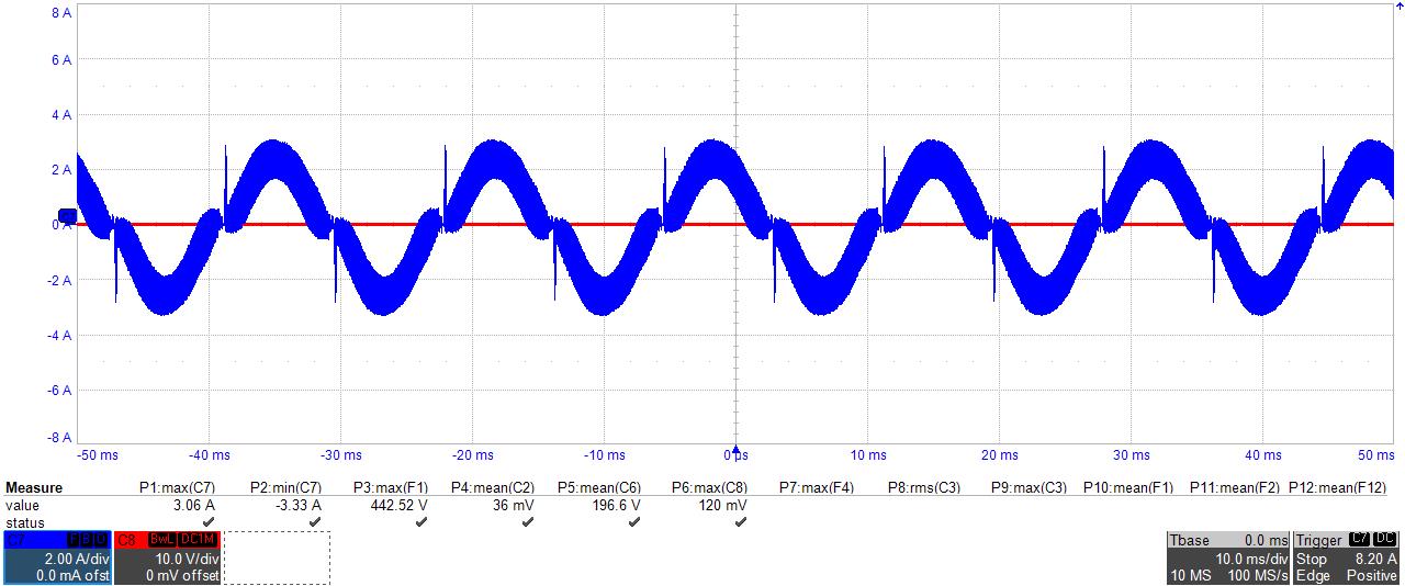
1.

However, although I used the same code in powersuite TIDA-01604, current spike always happens like the above figure.

So I tried to revise the below existing code. but I couldn't solve this problem.

Are there any solutions related to this problem?

case pwmSwState_negativeZeroCrossing3 :
// wait till certain positive threshold before moving to the normal operation

softstart_duty= softstart_duty+1;

softStartDeadBandFED=PFC_PWM_PERIOD - softstart_duty*50;

if(softStartDeadBandFED<dbFED_SetValue )
{
softStartDeadBandFED=dbFED_SetValue;
}

SET_PWM_DBFED(HIGH_FREQ_PWM1_BASE, softStartDeadBandFED );

state_slew++;

if(state_slew > state_slew_max && ac_sign_filtered ==0 )
{
gi.i10=0;
gi.i6=1;
gi.Ki=GI_PI_KI;
gi.Umax=GI_PI_MAX;
gi.Umin=GI_PI_MIN;
gi_out=0;

pwm_SwState.enum_pwmSwState=pwmSwState_negativeHalf;
SET_PWM_DBFED(HIGH_FREQ_PWM1_BASE, dbFED_SetValue);

state_slew=0;
}
break;

case pwmSwState_positiveZeroCrossing3 :
state_slew++;

softstart_duty= softstart_duty+1;

softStartDeadBandFED=PFC_PWM_PERIOD - softstart_duty*50;

if(softStartDeadBandFED<dbFED_SetValue )
{
softStartDeadBandFED=dbFED_SetValue;
}

SET_PWM_DBFED(HIGH_FREQ_PWM1_BASE, softStartDeadBandFED );

if(state_slew > state_slew_max && ac_sign_filtered==1)
{
gi.i10=0;
gi.i6=1;
gi_out=0;
gi.Ki=GI_PI_KI;

pwm_SwState.enum_pwmSwState=pwmSwState_positiveHalf;

SET_PWM_DBFED(HIGH_FREQ_PWM1_BASE, dbFED_SetValue);

state_slew=0;
}

break;

2. In state machine, I am curious about dutyPU=0.004f. Why this value is used in several case statements?

Thank you.

  • 1. In state machine, I am curious about dutyPU=0.004f. Why this value is used in several case statements?

    We use deadtime to reduce the pulse widths of the totem-pole PFC. The clamp is used to make sure and edge occurs, otherwise, 100% duty cycle can inadvertently result under certain conditions. Which may not be desirable.

    2. What type of voltage source are you testing with, what is the impedance? There will be some zero-crossing spike component 

  • Dear Manish,

    Thank you for your reply!

    I tested the converter with AC and DC power supply. But I used AC source based on this power supply.

    I didn't understand what type of impedance you mean?? Could you tell me how to measure that kind of impedance?

    I used four low-frequency SiC Mosfet(C2M0025120D) with two parallel structures like TIDA-01604.

    Also, I used two high-frequency SiC Mosfet(C3M0065100K) like TIDA-01604.

    Output Voltage bulk capacitor: 1mF

  • Dear Manish,

    1.

    After I tried to solve current spike, I could decrease the current spike.

    But, It was confirmed that the tendency of a spike in positive zero-crossing and negative zero-crossing was different.

     In case of negative zero crossing, soft-start algorithm sometimes didn't operate well like below figure.

    green : Drain source waveform of low frequency upper switch Q1

    red: gate source waveform of low frequency bottom switch Q2

    blue : Input current = Inductor current(my converter has only one phase) 

    pink : Drain source waveform of upper high frequency switch Q3  

    power : 350W

    BLUE shows -6.43 A minimum value.

    BLUE shows -1.XXX A minimum value.

    To confirm each case statement softstart operation, I put flags both case pwmSwState_positiveZeroCrossing3  and case pwmSwState_negativeZeroCrossing3. The figure shows different values.

    Is there any possible solution for me??

    I attached my case statement code.

    switch.docx

    2. I'm trying to increase the power level to 1kW. But, whenever I increase from 800w to 1kW, short-through always happens in high-frequency switch Q3,Q4. Also I increase the deadtime up to 0.4us(original deadtime is 0.2us)

    Is it because of the problem above?

    Thanks.

  • ok let me look through the changes you have done to the state machine. 

  • Just checking back on this, do you get both positive and negative spike at a positive zero crossing i.e. line going from negative to positive and vice versa?

    Or the issue more on the lines,

    sometimes around the zero crossing you are getting a spike and some times you do not?

    -Manish