This thread has been locked.

If you have a related question, please click the "Ask a related question" button in the top right corner. The newly created question will be automatically linked to this question.

TINA TI incorrect simulation result

Other Parts Discussed in Thread: LM837, INA332

I am trying to simulate a 6 stage op amp design. The last 4 stages will use a LM837 part. There in no macro model for this part. However I saw on the forums where a TI Engineer said a MAX410 part was close enough to use for the simulation.

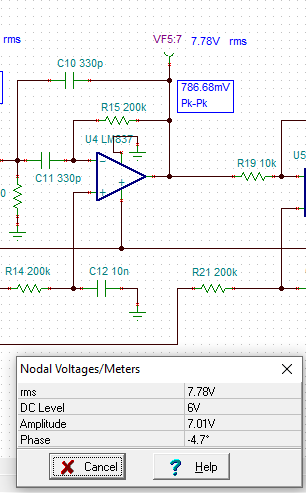
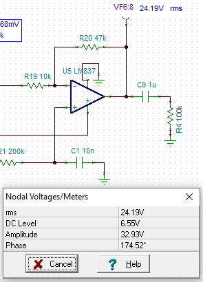
Then I run Analysis -> AC Analysis -> Calculate nodal voltages, node VF6:9 shows an Amplitude of 36.98 volts. Obviously with a 12 volt power supply this cannot happen.

What am I doing wrong? The TSC file is attached.

Thank you.INA332_620_MAX410.TSC

Ray

  • Hi, Ray,

    Our team will take a look at this issue and will provide a reply as soon as possible.

    Best regards,
    Luis Fernando Rodríguez S.

  • Hi Ray,

    LM837 has PSpice mode available both in its product folder and in our new PSpice for TI tool if you want to take a look.

    Attached is the TINA file with a macro-model I created based on the unencrypted PSpice model for your reference. (This is not an official TINA release model)

    Regarding the simulation results, I have some comments:

    • You must consider that last stage has ~4.7V/V gain, and input signal is actually 7VDC, the calculated nodal voltage is multiplying input 7VDC by 4.7 and gives ~32.9VDC result
               
    • I'll check on the resulting nodal voltage, as this is actually only showing the expected voltage based on the gain, not considering supply voltage.
    • By performing a transient simulation, you can see the output is actually clipping at ~11V


    Please let me know if you have any questions.

    Best regards,
    -Ivan Salazar
    Applications Engineer - Low Power Audio & Actuators

    INA332_620_LM837.TSC

  • Ivan,

    Thank you for the explanation. I was aware that the transient simulation gave the correct results.

    I was curious about the 32.93 volt output from the AC Analysis. Out of curiosity, I inserted a 1uF cap between R19 and the inverting input of U5 so there would be no DC voltage present. The Nodal Voltage fields now show 0V for the DC level at the node between C9 and R4. However, I still see the 32.93 volt output at that node. What exactly does the Amplitude field refer to?

    I will download the Pspice for TI tool and give it a try.

    Ray

  • Hi Ray,

    A series capacitor is removing DC component, thus calculated DC level would be 0.
    The nodal analysis considers both AC and DC, for the amplitude it calculates the voltage amplitude not considering circuits supplies but only the gain; if you set your input stimulus to 0V amplitude then you'll get 0 amplitude and only DC level.

    Let me know if you have any further questions.

    Best regards,
    -Ivan Salazar
    Applications Engineer - Low Power Audio & Actuators

  • Thank you Ivan. That explains how it works.

    Ray