This thread has been locked.

If you have a related question, please click the "Ask a related question" button in the top right corner. The newly created question will be automatically linked to this question.

PSPICE-FOR-TI: # Error # PSpice Model Parameter # Using Vendor LED Model

Part Number: PSPICE-FOR-TI

I am trying to use a vendor's PSpice LED Model in PSpice FOR TI Simulation (Transient Analysis).

Model does not netlist due to  ERROR -- 'mfg' is not a model parameter name.

Is Model valid for use in PSpice FOR TI?

If this LED model can not be used, can I remove MODEL parameter to fix MODEL or generate similar PSpice MODEL using generic Spice syntax?

DSN file is only available confidentially.

  • Hi Charles,

    Please contact model vendors for support. MFG is not a valid model parameter for PSpice.

    You can use the built in modeling application to model certain components if needed.

    Thanks,
    JC

  • Hi JC,

    Not a viable solution since support from vendor is not guaranteed even though vendor lists this as a PSpice model.   How can I edit PSpice model to remove MFG parameter?

    Alternative 1: Cadence has a number of PSpice Models for LEDs:

    How can I use these libraries since I only have PSpice for TI?  Can the diode parameters be adjusted?

    Alternative 2: do you have a generic diode model for PSpice for TI with adjustable parameters to fit the current vs voltage (DC) curve?

    Thanks,

    Charlie

  • Hi Charlie,

    Please take a look at this FAQ to see if the "generic model" satisfies your needs: e2e.ti.com/.../973740

    Sorry, TI cannot make recommendations on how to edit a 3rd party model.

    Regards,
    JC

  • I do not see the  icon,.  The Modeling Application box was greyed out.  Is this supposed to be available for any PSPICE-FOR-TI user? 

    Thanks,

    Charlie

  • Charlie,

    Sorry, I cannot see any of your screenshots. Would you please re-attach them using the paper cllp icon? 

    Thanks,
    JC

  • After a few tries, I got access to the Modeling Application.  It is often greyed out even when I only have schematic open.

    Within the Modeling Application, it seems the only diode with parameters is the simple Power Diode model below.

    How can I access PSpice diode models with traditional spice parameters to represent the curvature of the diode IV curve as well as the series resistance?

    BTW, I did get vendor diode model to work by editing the .lib file as well.

    .SUBCKT POWER_DIODE_P np nn PARAMS:
    + I_Rev_Leak=1e-5
    + CT_Zero_Volts=300pF
    + V_BR=600
    + Vj_Knee = 0.90
    + Vj_Spec = 1.6
    + If_Spec = 6
    .PARAM VJ_nom = 0.35
    .PARAM Rs_eq  = {ABS((Vj_spec - Vj_Knee)/If_Spec)}
    .PARAM V_int = {ABS(Vj_Knee - VJ_nom)}
    V_D1 = np np_1 {ABS(V_int)}
    D1 np_1 nn D1exp
    .model D1exp D Is={I_Rev_Leak} Cjo={CT_Zero_Volts} Rs= {Rs_eq} BV={V_BR}
    .ENDS

  • Hi Charlie,

    To use the SPICE primitive diode model, you can place a symbol "Dbreak".

    Thanks,
    JC

  • Placed symbol but am having problems adding Model Library file matching implementation property.  I made a Dbreak.lib file in same directory as other Model Libraries but can't add it to the Model Libraries tab (greyed out, see /cfs-file/__key/communityserver-discussions-components-files/234/IssueWithModelLibraryAddFile.docx ).  PSpice Software runs very slowly (even GUI without simulating) although other applications run fine with wired internet.

  • Hi Charlie,

    The default implementation of the Dbreak symbol is "Dbreak". If you right click the instance you placed and select "View PSpice model", the LIB file containing the model (dictated by the library configuration in the active sim profile) will be shown.

    If you have your own diode model, edit the Dbreak instance's implementation property to the name of that model, then include the corresponding LIB file in the active sim profile.

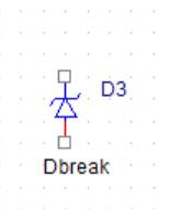
    1. Instantiate the part DbreakZ. It will call a model named “dbreak” during simulation:

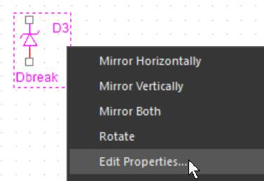
    2. Select the instance and right click, then select “edit properties”:

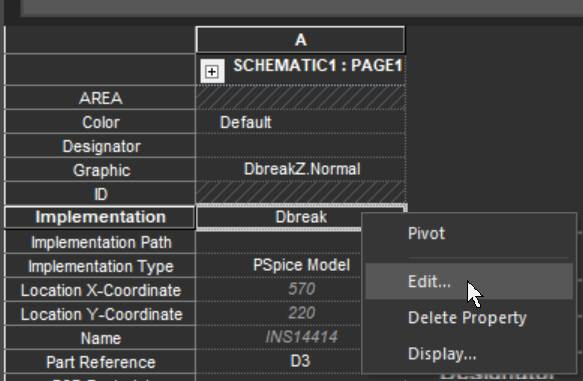
    3. Right click the property “Implementation” and select “Edit”:
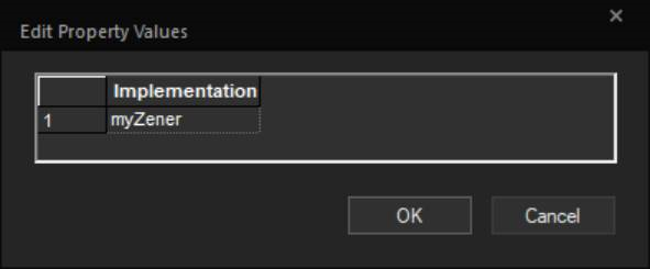
    4. Enter the name of the diode model you want to use:
    5. OK the pop-up, close the property editor and OK the undo warning.
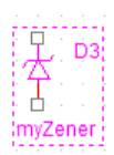
    6. This instance will now call the model "myZener":
      D_D3 1 2 myZener

    Regards,
    JC

  • Do not close issue since I am having convergence problems running simulation with diode per your recommendations (DC convergence fails).  The circuit is an TI opamp-based LED current driver using a TI voltage reference.  Circuit prototype has been built and works as expected. 

    Next step will simplify circuit to a voltage source, series resistor and diode (forward biased LED model).

  • Hi Charles,

    Sure we are not closing it.

    Do you want to share your design with us for further troubleshooting? You can archive it and attach it here, or send it to me via a private message.

    This is how to archive a project: https://e2e.ti.com/support/tools/sim-hw-system-design/f/234/t/969692.

    Thanks,
    JC