This thread has been locked.

If you have a related question, please click the "Ask a related question" button in the top right corner. The newly created question will be automatically linked to this question.

PMP10835: How can I make a coupled inductor in "PSpice for TI" from two uncoupled inductor?

Part Number: PMP10835
Other Parts Discussed in Thread: TPS61165

Sometimes component manufacturer does not publish model for a given part, but they say, that it is easy as you can see below in that situation.

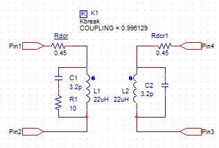
Coilcraft does not have coupled inductor model, but they sent me a link, that it is possible to make it from a two uncoupled inductors via SPICE "K" directive (as “K” statement to couple the inductors) in LTSpice.

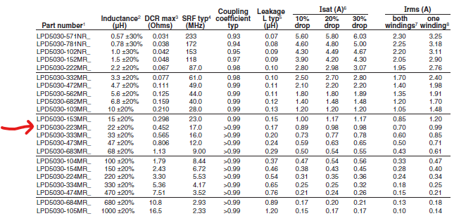
I would like to simulate SEPIC SMPS with coupled inductor from two uncoupled models. In my case, it should be meaning of directive "K1 L1 L2 0.99", where L1 and L2 are uncoupled inductors on schematic, and 0.99 is the coupling factor. e.g. to model LPD5030-103MR_ from here LPD5030 Series Shielded Coupled Power Inductors | Coilcraft

Coilcraft has uncoupled inductor models as PSpice lib here:  Spice Models / S-parameters | Coilcraft

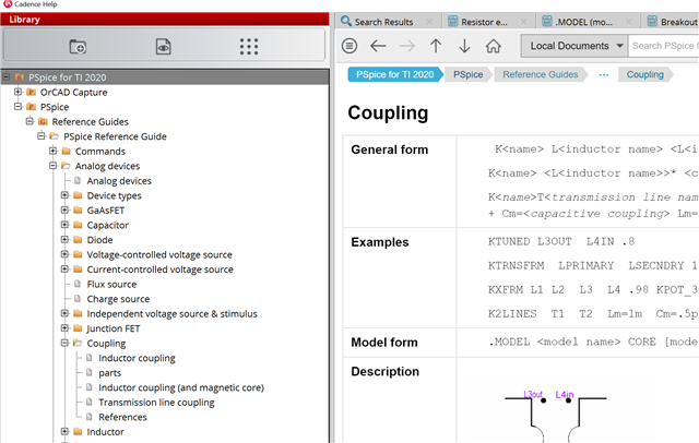
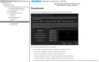
How is it possible to do it in "PSpice for TI"?

Any workaroud could be appreciated.

Reference link:

Using Transformers in LTspice/Switcher CAD III | Analog Devices

"To simulate a transformer in your LTspice/SwitcherCAD III simulations, just draw each winding of the transformer as an individual inductor. Then add a SPICE directive of the form K1 L1 L2 L3 ... 1. to the schematic. That’s basically it!"

PS: I'v used TPS61165 BOOST reference design in PSpice for TI, and it was modified for SEPIC as PMP10835 (LED Driver SEPIC Converter (9.9V@0.24A) Reference Design with two uncoupled inductor).

Attila

  • Attila,

    The "K" coupling term is called "K_Linear" in the component search  list. Please see its location in the attachment.

    regards,

    John Betten

  • Hi John,

    How can I use it in practice? To merge L1 and L2 inductors on the sheet.  I can not edit its property for L1 and L2.

    Other:

    I am trying to use single coupled models from PSPICE Modelling Application as alternate workaround, but I get very fake simulation results after SEPIC simulation to comparing with MATLAB simulation and estimated simulation results.

    What is wrong?

    Could you tell me what model type should work well for LPD5030-223 inductor?

    VerA: Using of Two Winding transformer type

    VerB: Using of Forward transformer type

    Unfortunately, I can not see the link between L_leak and K coupling factor at models. There is a big contradiction on above models between used leackage inducrance and coupling factor.

    Infos for understanding:

    SEPIC SMPS:

    Coupled Inductor parameters:

    Attila

  • Append:

    I can not merge the two uncoupled inductors and K-Linear part with L1="L1" and L2="L2" property, because they mean different parts on netlist, and I get errors.

    Uncoupled inductors with reference designator of "L1","L2" on the sheet have name of "X-L1","X-L2" and K1 refers to "L_L1","L_L2". So they are different.

    **** INCLUDING Steady_State.net ****
    * source TPS61165_TRANS
    R_R1 N14815114 N14815084 1u TC=0,0
    C_C2 0 N14815114 0.1uF TC=0,0
    X_C3 VOUT 0 CESR PARAMS: C=10u ESR=2m IC=21.3 X=1
    V_V11 CTRL 0
    +PULSE 0 5 0.1m 10n 10n 12.5u 25u
    R_R2 0 N14814956 1 TC=0,0
    V_LED N14814952 N14814956 0
    C_C1 0 VBAT 4.7u TC=0,0
    V_VBAT VBAT 0 5V
    X_C4 N14834612 N14816909 CESR PARAMS: C=1u ESR=2m IC=21.3 X=1
    X_U2 N14847862 N14814952 WLED
    X_U3 VOUT N14847862 WLED
    X_U1 N14815084 CTRL N14814952 0 N14816909 VBAT 0 TPS61165_TRANS PARAMS:
    + CODE=32 EASY_SCALE=1 SS=1
    D_D1 N14834612 VOUT DD
    X_L1 VBAT N14816909 LDCR PARAMS: L=22u DCR=400m
    X_L2 0 N14834612 LDCR PARAMS: L=22u DCR=400m
    Kn_K1 L_L1 L_L2 0.99

    **** RESUMING Steady_State.cir ****
    .END

    ERROR(ORPSIM-15090): device L_L1 is undefined

    ERROR(ORPSIM-15090): device L_L2 is undefined

    ERROR(ORPSIM-15090): device L_L1 is undefined

    ERROR(ORPSIM-15090): device L_L2 is undefined

    Attila 

  • Attila,

    First of all, the detailed documentation is shipped with the tool. You can find it by clicking Help -> Documentation, then search inductor coupling:

    By reading this and looking at your netlist, I suspect that this statement only accept primitive inductor for L1 and L2, while in your netlist, the two inductors are instances of the LDCR subckt which models parasitic in addition to the inductor itself. Hence the simulator complaints that it cannot find those inductors.

    The obvious solution is to replace X_L1 and X_L2 with primitive inductors and use their names on the K statement.

    Does the K statement support hierarchical reference to the main inductors inside X_L1 and X_L2? I am not sure but it's worth trying. If you do that, please let us know what you find out.

    Thanks,
    JC

  • Hi JC,

    If I replace LDCR models to generic (primitive) inductors, then K-statment works fine.

    It seems, K-statment generates references with "L_" prefix, which correlates the inductor prefixes.

    L_L1 VBAT N14870693 22uH
    L_L2 0    N14851468 22uH

    Kn_K1     L_L1 L_L2 0.99

    The problem, that I can not control the naming convention, neither in inductor models, nor in K-statement. 

    If I use 3th party models, then the "X_" of inductor prefix and the non-editable "L_" of K prefix  will never met in the netlist.

    When I replace the inductors to target Colicraft Inductor models then I get similar results. Coilcraft inductors are with "X_L1" and "X_L2" of prefix in netlist. So it does not work again.

    X_L1  N14870693 VBAT LPS4018-223 PARAMS: CPAR=2.5PF IND=22UH
    X_L2  N14851468 0 LPS4018-223 PARAMS: CPAR=2.5PF IND=22UH

    Kn_K1 L_L1 L_L2     0.99

    I think it is not possible to use the recommended K-statment for 3th party uncoupled inductor models. I need have an other alternate way.

    There is a remaining problematic point. For using K-statement, the used inductors have to be DOT. The 3rty party Coilcraft model was published as single uncoupled inductor, so they don't have DOT.

    >Does the K statement support hierarchical reference to the main inductors inside X_L1 and X_L2?

    Where can I see it?

    *======================================================================
    * SPICE Model generated by Coilcraft
    * Coilcraft Part Number : LPS4018-223
    * Inductance = 22uH
    *======================================================================
    * Model Parameters:
    * Valid Frequency Range = 0.0001GHz-0.04GHz
    * Ambient Temperature = 25 degC
    * DC Bias Current = 0 A
    * Non-Linear Frequency Dependent Approximation
    *======================================================================
    .subckt LPS4018-223 port1 port2 PARAMS: Cpar=2.5pF Ind=22uH
    X1 port1 port2 Model1A PARAMS:
    + R1=36
    + R2=0.33
    + C= {Cpar}
    + K1=0.0001
    + K2=5.41
    + K3= {Ind}
    + K4=0.161
    + K5=0.0000099
    + L=0
    + Is=0
    + a=0
    + L_Z0=0
    + L_EL=0
    + L_F0=0E6
    .ends LPS4018-223

    Other comments: 

    - I get false simulation results with using primitive L and Rs combination. So replacing Ti's LDCR model (22uH, 0.4 Ohm) with two primitives (L=22uH and R=0.4 Ohm) is not the same results. The result is a false simulation.

    - LDCR model is embended model in TI's geniune TPS61165 reference design.

    Any idea to step forward?

    Attila

  • Attila,

    With that last question in my reply I was suggesting you do this (without replacing the LDCR with primitive inductor):

    Kn_K1 X_L1.L X_L2.L     0.99

    If you look at the LDCR subckt, it contains a primitive called L, hence X_L1.L and X_L2.l are the hierarchical references to those 2 primitives.

    I am not 100% sure if this would work. Please give this a try. 

    Thanks,
    JC

  • Hi JC,

    It does not work.

    In case of "X_L1.L": the generated reference name is "L_X_L1.L"

    "Kn_K1         L_X_L1_L L_X_L2_L     0.99"

    ERROR(ORPSIM-15090):  device L_X_L1_L is undefined

    In case of "L1.L": the generated reference name is "L_L1.L"

    "Kn_K1         L_L1_L L_L2_L     0.99"

    ERROR(ORPSIM-15090):  device L_L1_L is undefined

    And so on. The prefix is constant "L_". The name is L_<K-state parameter>

    PS: I don't have model of LDCR. It is only available for me as Design Cache. Is it possible export them from design?

    Attila

  • Attila,

    To view the LDCR model, select L1, right-click and select "View PSpice model". A new tab will be opened showing the LIB file bound to the component (automatically jump to the definition line, being SUBCKT or MODEL).

    Regards,
    JC

  • Hi JC,

    There are unresponsed themes above. I asked about transformer models too.

    Which transformator model should I use?

    Which is correct inductor model types for coupled Coilcraft's inductors ? Two Winding transformer type, or Forward transformer type?

    Could you tell me what model type should work well for LPD5030-223 inductor?

    What is the difference between both of transformer type? The simulation results are not the same with using of both of them transformers.

    More detalis are above.

    Attila

  • Hi Attila,

    I believe these questions should be answered by the model vendor, Coilcraft. If Coilcraft has any question in particular for PSpice regarding these models, we will be happy to assist.

    Thanks,
    JC

  • Hi JC,

    I don't aggre with you. I asked you give me more details about those PSPICE transformer models. Unfortunately, description of models are not clear for me. I would like to understand them. So this is PSPICE related question.

    Attila

  • Hi Attila,

    Please take a look at the documentation to see if it contains the information you need. Click Help -> Documentation, select PSpice, Reference Guides, PSpice Reference Guide, Analog Devices, Coupling:

    Regards,
    JC

  • Hi JC,

    You has misunderstood me.

    I am talking about transformer models (under PSPICE Modelling Application). Its has very narrow details in help system about Two Winding transformer type, and Forward transformer type.

    Attila

  • Hi Attila,

    I read your original post.

    Can I interpret your question as "how to use K1 L1 L2 L3 in PSpice for TI where L1 L2 L3 are coilcraft models"?

    Thanks,

    JC

  • Hi JC,

    Basicly, my response is "yes", but unfortunately it is not possible to do it. That's why I have turned toward transformer models.

    I have been connected to Coilcraft and they confirmed me about this:

    1. Coupled inductor models are not available at Coilcraft.

    2. Uncoupled inductor models are available at Coilcraft, but they could not use as "K1 L1 L2 0.99".

    3. I have to model the coupled inductors in one of two ways (3.1 or 3.2)

    3.1. from generic L models as these ones

    3.1.1. simple (two generic inductors with the "K" coupling term is called "K_Linear" or "Kbreak")

    3.1.2. complex like this (where Lleak and SFR is taken account too)


    3.2. to use generic transformer models (this is my question now,  i.e. to know the transformer models of PSPICE Modelling Application)

    Attila

  • Hi Attila,

    Would you please provide the uncoupled inductor model from Coilcraft?

    Thanks,
    JC

  • I used this lib from Coilcraft. Coilcraft_PSpiceLib.zip

    Model libraries for PSpice® | Coilcraft

    More details were sent in private.

  • Attila,

    I'll take a look at your message. Meanwhile, here's the notes on the transformer model provided in the modeling application.

    You can simply put a transformer in your schematic, then right-click and select "view PSpice model". This will reveal the actual circuit used. for example:

    .SUBCKT FLB_Model P1 P2 S1 S2
    * Model generated on 2021 May 24
    * MODEL FORMAT: PSpice
    * MODEL Type: FLB_Model
    RP1 P1 PI 10m
    LP1 PI P2 1m
    LS1 S1 SI1 1.0000e-1
    RS1 SI1 SI2 10m
    LL1 SI2 S2 100n
    K1 LP1 LS1 1
    RG1 S2 0 1G
    .ends FLB_Model

    This is very different from the schematic you drawn so it does not model your particular coupled inductor well.

    Regards,

    JC

  • I known it, but it is not clear for me, what the help system says. How is it possible to use 100% coupling factor with 100nH leakage inductance. So I don't understand these models. 

  • Got it. You are referring to these statements:

    I've mentioned it to the developers and requested more details added.

    Thanks,
    JC