This thread has been locked.

If you have a related question, please click the "Ask a related question" button in the top right corner. The newly created question will be automatically linked to this question.

Webench DC Bias Correction For Ceramic Capacitors

Expert 2041 points
Other Parts Discussed in Thread: TPS54240

I am questioning the Webench simulations with respect to DC Bias on ceramic capacitors.  Hopefully I've made a wrong assumption and I just need to be set straight.  I have constructed an example that shows it isn't working as I expect it should.

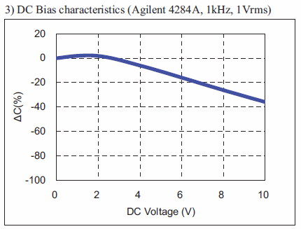
I looked for a design that uses ceramic capacitors for its output, and in particular one that uses a small-sized package which would be more apt to show the effect of DC bias than a larger one.  I found a TPS54240 Webench design that uses six 10µF 0805 caps for the output.  The output of the design is 5V and the capacitors are rated at 10V.  The capacitors are X5R 10%, which should show a pretty good DC bias effect at 5V.  I looked for data on the Kemet website but could not find the DC bias curve, but I finally found the info in their Kemet Spice program (http://webspice.kemet.com/).  It looks like that particular 10µF 10V capacitor (C0805C106K8PACTU) has a capacitance of 6.5µF when a DC bias of 5V is applied.  That is a 35% reduction which seems significant to me.

I made four Webench designs and ran simulations for each.  Each time I started a new design from scratch because I found Webench gets messed up if you repeatedly make changes to custom components.  I compared the resulting schematics and I didn't see any component changes other than the output capacitor.  Here are my specifications:

I chose the TPS54240, and did not change anything except for the output capacitor.  Here are the four combinations I chose.  In all cases there were 6 capacitors in parallel.

1. 10µF 10V (No changes to the default design.  It is not a custom component.)
2. 10µF 390V
3. 6.5µF 10V
4. 6.5µF 390V

390V was the maximum value Webench would allow for the DC rating of the capacitor.  For the 3 cases in which I made a custom component, I left all of the parameters the same and only changed the voltage and the capacitance as needed.

The voltage rating of the capacitor didn't seem to affect the simulation results much.  I expected the results of the 10µF 10V and 6.5µF 390V simulations would be very similar if the Webench simulation was applying a compensation for the DC bias.  A 390V capacitor wouldn't lose hardly any of its capacitance at a DC bias of 5V.

Here are plots of the Load Transient simulations:

The two 6.5µF plots look same, as do the two 10µF plots.  I can barely see the effect of the voltage in the simulations.  If it does not apply an accurate correction, the suggested capacitor values may be off by quite a bit.  Does anyone see a mistake in my experiment?  I can post more simulation plots if anyone wants to see them, but you should be able to try this yourself by doing what I described above (I assume Webench will create the same default design).

Thanks,

Greg

  • Can anyone confirm this?  In another forum posting I happened to bring up the issue of DC Bias on capacitors.  After I posted a possible solution to the problem (assuming this is a problem), I thought I should have probably posted it here.  This is what I said:

    I think you might want to consider a simple approach to addressing the issue. Since there isn't such a thing as a formula that fits all ceramic capacitors, I think it is best left to the user to manage. Capacitors in your library can be fully characterized, but of course you couldn't do a very good job at correcting for a custom component. I think you should include an option in the "Create a Custom Part" dialog to turn off DC Bias Correction. This would allow the user to enter the exact capacitance their self. With DC bias correction turned off for that component, the simulation would be perfect. It really would be the right thing to do because it is really impractical for you to characterize every capacitor manufactured today. Alternatively, it might be better to allow the user to choose a percentage correction for DC Bias rather than turning it off. That way the capacitor's capacitance value is documented, and the effective capacitance can be accurately applied in the simulation.

    By default the correction would be set to 100%, which wouldn't be far off from what it appears to be right now.  What I really want to know is if I should correct for it myself by entering a corrected value.  Or am I fooling myself by doing that and only introducing a problem I'm not aware of?

    Thanks,

    Greg

  • In the other thread I also posted some interesting data on a couple of capacitors that illustrate how wildly DC bias affects different capacitors.  This is what I said:

    For anyone reading this thread that is not very familiar with the effect of DC bias on a ceramic capacitor, I have found a few examples that illustrate how radically different it can be from one capacitor to another. This is why I said before that it isn't possible to make a very accurate formula to correct for DC bias. Here are two capacitors from the same manufacturer that have the same exact case size, same capacitance, same tolerance, and same dielectric, but their DC bias performance is surprising to me. At 10V DC bias, the capacitor rated for 10V is only down about 40%. The capacitor rated for 25V is down about 70% at 10V. And to top it off, the 10V capacitor costs less.

    Samsung CL31A106KPHNNNF
    1206, X5R, 10uF, ±10%, 10V

    Samsung CL31A106KAHNNNE
    1206, X5R, 10uF, ±10%,  25V

    As a disclaimer I need to say that I am not an authority on capacitors, and it is possible that Samsung made a mistake in their data sheet.  Or I made a mistake in interpreting the data.

    Greg