This thread has been locked.

If you have a related question, please click the "Ask a related question" button in the top right corner. The newly created question will be automatically linked to this question.

what can we use instead of TLV3502 for hardware fault detection.

Other Parts Discussed in Thread: TLV3502, OPA2350, OPA2340, OPA350, OPA340

hi every one 

good day!

my H/W is HV motor control kit (yellow board).

for fault detection TLV3502  was used .

shall we use opa2350 or opa2340 instead of it?

what is the benefit of using TLV3502 in fault detection section?

which factor should we put on consideration if we want to use another opamp?

thanks for attention

Dave.   

  • Dave, 

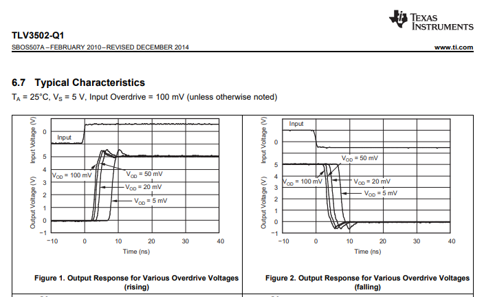
    TLV3502 is a high-speed comparator and NOT an op amp.  Because comparators are essentially uncompensated op amps, no op amp can match the transition time of a comparator’s output for a given quiescent current, which may be critical in your fault detection circuitry.

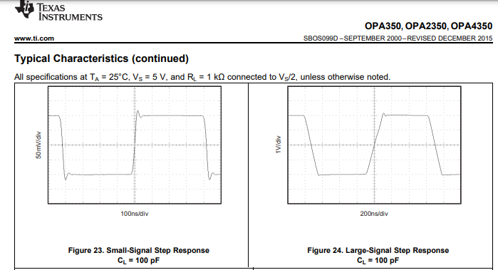
    Thus, my question to you is why do you want to replace TLV3502 on the first place.  And if you have a good reason for doing so why do you try to replace a comparator with an op amp?  Having said that, OPA350 has faster slew rate than OPA340 but because they are op amps their transistion speed is nowhere close to TLV3502 comparator- see below.

    your 

  • Thanks for your help 

    now I figure out that  comparator are different from op amps. but I thought Op amps also compare between + and - pins am I right?

    what you point it out is about the speed of reaction ?   propagation delay am I right?

    input to out put Rising time ~4ns and Falling ~5ns

    but for Op Amp opa2350 is ~100ns is that what you mean?

    I would be happy if you help me more thanks .

    Dave.

  • Yes, that is correct.  If you use an op amp in open-loop configuration (with no negative feedback), it is essentially going to act the same as a comparator.  BUT since the output voltage rate of change (slew rate - SR) is limited by the tail current, Itail, biasing the input differential pair and the Miller capacitor, Cc, used to set the bandwidth, SR=Itail/Cc, the op amp response time for a given Itail will be much slower than that of a comparator because the latter uses little or no cap, Cc, for its internal compensation.

  • Thanks Marek

      for useful information do you have any reference to get more information about that .

    and some thing that really surprised me is in HVkit motor controls in current fault detection the output of OPA2350 is too spikey , in every HV switching the spikes of it are around 2 volts assuming that the current drawing from motor is very little the output of OPA2350 will be  ~1.65v ,but the spike due to switching is around  (from 2.65v to 0.65v) the reference pin of TLV3502 is connected to potentiometer and assuming set to 2.3v ,how TLV3502 do not consider spike as a signal and set the out of  TLV3502  ,in spite of High speed comparator how would it be possible to not to consider Spike as a signal ?

    would you please explain more about that ?

    Dave.

  • Dave,

    In motor control applications, one may run into extremely fast inductive kickbacks, which are typically controlled with a snubber circuit (resistor+capacitor to ground).  If the input voltage spike is of very short-duration (e.g. 1ns), TLV3502 may not be able to react fast enough.  To say anything more on the topic, I would have to see the actual schematic implementation of the fault detection circuit.

  • hi dear lis

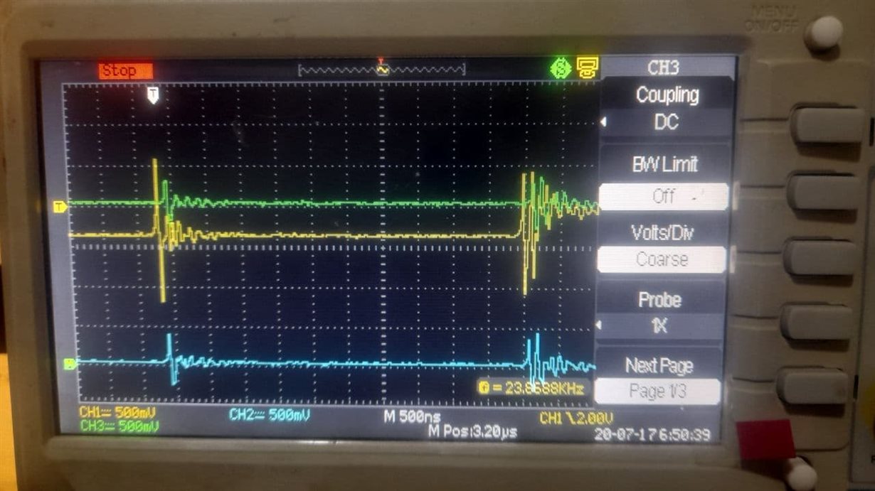
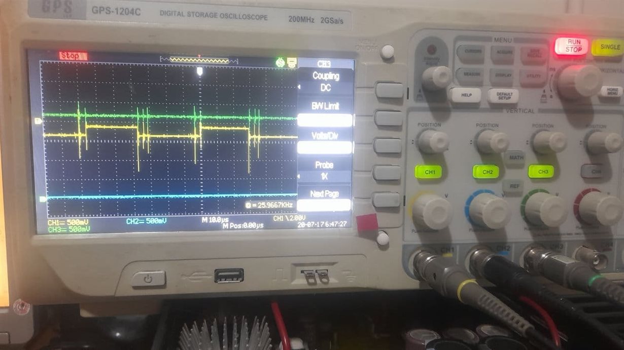
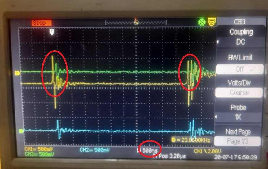
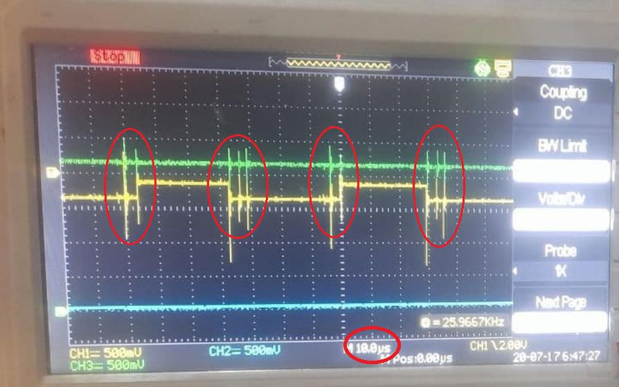
    Green =refence fault 

    yellow = current feed back from PWM signal

    blue = output of TLV3502

    some thing that really shocked me is spike time  TLV3502 do not consider it as a signal!!!! 

    why is that ?

    in first picture we can see reference and signal are interfering due to spike , but the output of TLV3502  is not consider this as "SET" condition.

    Dave..

  • Dave,

    In the top scope picture PWM signal (yellow trace) seems to intersect the reference voltage (green trace), thus triggering the comparator (blue trace) - see below.

    However, this seems NOT to be the case in the second pic - see below. The yellow PWM signal seems to stay below the green tripping point reference voltage. In order to make sure we don't miss something here, please change the time scale on the lower scope picture to the same 500ns scale used in the picture above.