This thread has been locked.

If you have a related question, please click the "Ask a related question" button in the top right corner. The newly created question will be automatically linked to this question.

TIDA-00792: Wrong voltage being shown on BQStudio

Part Number: TIDA-00792
Other Parts Discussed in Thread: BQSTUDIO

Hello,

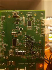
I am using 13 cell-configuration for TIDA-00792.

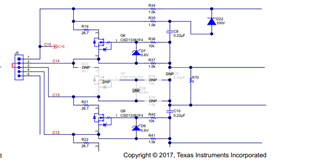
Following components were not populated: R20, Q7, R38, R39, D8, C9 R25, Q12, D13, R50, R51, C14.
R71 and R72 are populated as per design recommendations.
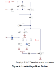
Also, the sensing/balancing leads are shorted externally as recommended in the Multi-Cell 36-48V Battery Management System Reference Design's figure 3 for unused cell connection.
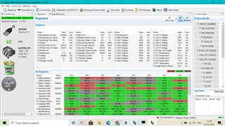
Voltage across:
C32 :  1.79V
C12 : 1.79V
C11 : 5.75V

J5-5 and J6-1: 3.87V

Is the AFE Cell configuration correct? 
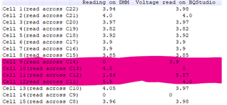
ADC seems to be working fine, I suspect the fault's elsewhere. We should be getting 3.87 V across C11 but we're getting 1.79V
What could be causing? 

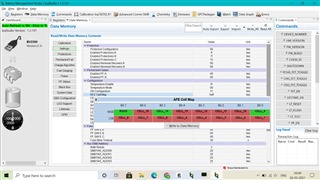
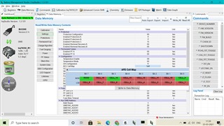
Attaching images from BQStudio:

Thanks and regards,

Nishil Bhavsar

  • Hi Nishil,

    R71 and R72 are populated? Do you mean R70 and R71? I think R72 would be shorting the wrong cell inputs.

    Best regards,

    Matt

  • Hello Matt,

    I am sorry that was a typo and yes you're correct. I didn't populate R70 but populated R71 and R72.
    Why am I seeing voltage across: C32 as 1.79V only and same goes for the rest, C12 : 1.79V, C11 : 5.75V?
    I am getting the right voltage at the cell inputs on J6 but at the output of the filter circuit I'm getting this dropped voltage.

    Ideally we should be seeing C32: 3.8V, C12: 3.8V and C11: 5.75V

    Why could this be happening?

  • Hi Nishil,

    I'm still a little confused. Are you sure you mean C32? 

    All of the cell voltages should measure the same. Have you measured at the VC pins on the board? Have you connected the cells to the correct terminals. It seems something is not correct on the hardware since you are seeing half of the expected voltage.

    Best regards,

    Matt

  • Hello Matt,

    I am seeing across C23: 1.8 V, C12: 1.8V, and C11: 5.75V.
    Any reason why this could be happening?

    Can you please share a reference schematic for using 13S configuration using TIDA-00792?
    Which components to be mounted and which not to be?


    Is this correct: components not populated: R20, Q7, R38, R39, D8, C9 R25, Q12, D13, R50, R51, C14 ?

    Also, the leads are shorted externally as recommended in the Multi-Cell 36-48V Battery Management System Reference Design's figure 3.

  • Hi Nishil,

    Something must be connected incorrectly. The list of components you have not populated looks correct and it looks like you have followed the correct instructions for shorting the leads externally.

    However, it should not possible to see these voltages. I suggest measuring each of the voltages at the J6 and J5 connectors, measure the voltages of VC5X, VC10X, BAT, CAP1, CAP2, CAP3. Maybe one of the wrong components were removed if the labels on the silk were shifted?

    Matt

  • Hello Matt,

    Can you please help me figure out the discrepancy in readings taken across ADC input capacitors using DMM and readings shown on BQStudio? 
    Do we only have to configure AFE Cell Map register for proper reading of voltages or we need to configure other parameters as well?

    Also, I checked voltages at:
    VC5X : 19.6 V
    VC10X : 15.96 V
    VC15X : 15.5
    BAT : 51.1 V
    CAP1(across C33) : 3.28 V
    CAP2(across C34) : 3.28V
    CAP3(across C35) : 3.28 V
    They appear to be correct to me.

    I am attaching images from my PCB for reference

    Also, I am using the low voltage boot option, so these components weren't populated apart from the previously mentioned components

  • That is good that your voltages at BAT, VC10X, VC5X, CAP3, CAP2, CAP1 are all measuring the correct values.

    It seems like something is installed incorrectly in the area around C12/C11 because the voltage is being divided strangely. Is it possible one of the components is not making good contact or was uninstalled by mistake (maybe the silk labels are shifted)?

    There are no other settings that need to be changed in BQStudio.

    Regards,

    Matt

  • Hello Matt,

    The IC pin was damaged, we replaced the IC and things started to work as expected.
    I suspect damage caused to the IC was due to the design consideration mentioned between pages 19-21!

    Thanks and regards,
    Nishil Bhavsar

  • That's great to hear! Thanks for the update Nishil.

    Matt