This thread has been locked.

If you have a related question, please click the "Ask a related question" button in the top right corner. The newly created question will be automatically linked to this question.

TIDA-01023: Firmware for my desired reference and sample frequencies

Part Number: TIDA-01023
Other Parts Discussed in Thread: LMK04828, , ADC12DJ3200EVM, LMX2594, TIDA-01021

Hello,

I am following "TI Designs: TIDA-01023 High-Channel-Count JESD204B Clock Generation Reference Design for RADAR and 5G Wireless Testers" to clock my ADC12DJ3200EVM boards. The document instructs to load "1023_LMK04828EVM_Master_3GREF_300MOut_37.5MSync_Output_Distribution.tcs" in TICSPro to program the LMK04828 in distribution mode. I would like this file modified to use a 2 GHz reference and also allow for a third slave clocking board on DCLKout4 and SDCLKout5.

Additionally, the document instructs to load "1023_BRDx_LMK04828_300MREF_300MFCLK_37.5MSYSREF.cfg" in the HSDC TID GUI. I already have firmware for my clocking boards that is working with my ADC12DJ3200EVM boards, so I would like the attached firmware modified to work with the LMK04828 reference source, keeping the output clocks the same if possible so that I can continue to use the same firmware for the LMX2594 and my ADC12DJ3200EVM boards. I have attached the LMX2594 firmware that I am currently using as well.

Thank you,

Alex

1021_JMODE0_LMK04828_10MREF_200MFCLK_10MSYSREF.cfg

1021_JMODE0_LMX2594_A_B_2GCLK_10MREF_10MPFD.cfg

  • Hello Alex,

    From the TIDA-1023, I didn't actually find the .tcs file.  Was that supposed to be listed in that software folder?

    Also, was there something specifically that was preventing you from making the changes?  I'd like to understand where the challenges are in the software that we can improve or provide better documentation for.

    . I would like this file modified to use a 2 GHz reference and also allow for a third slave clocking board on DCLKout4 and SDCLKout5.

    I'm thinking this should be as simple as typing 2000 MHz into the CLKin1 box and then enabling the DCLKout4 and SDCLKout5 outputs.

    The .cfg files appear to be a hex address + hex data output format of the register information.  Currently in TICS Pro if you use file --> export hex registers you get a text file that is similar and would need some changes.  A text editor with regular expression search replace (like Notepad++) would be able to convert the format.  I could give you the patterns.

    * Perhaps one of the software improvements for TICS Pro would be to support this .cfg format?

    73,
    Timothy

  • Hi Timothy,

    It could very well be as simple as typing 2000 MHz into the CLKin1 box and then enabling DCLKout4 and SDCLKout5 outputs. I should have made it more clear that I'm not sure where to find the original "1023_LMK04828EVM_Master_3GREF_300MOut_37.5MSync_Output_Distribution.tcs" either.

    I think generating the .cfg files could be a bit more complicated. In the past, we had Ajeet Pal generate the files for us. Perhaps I should have responded to that thread or referenced it here. Here is a link

    https://e2e.ti.com/support/data-converters/f/data-converters-forum/772052/adc12dj3200evm-tida-1021-sync-board-external-oscin-option

    Thank you,

    Alex

  • Hello Alex,

    Looking at the 1021_JMODE0_LMK04828_10MREF_200MFCLK_10MSYSREF.cfg file, it appears all that's required is the text "LMK04828" and then the full configuration as a hex export from TICS Pro.  For the record to any who may read this thread later, see my description below on how to change formats with an editor that supports regular expression search replace such as Notepad++.

    The file 1021_JMODE0_LMX2594_A_B_2GCLK_10MREF_10MPFD.cfg shows a bit more flexibility.  It appears the plain text line of the part number, followed by the registers you want to program (in the above format) is what is happening here, with % as a comment that can be provided at the end of a line containing register info or on it's own line.  Note at the end of this file it writes some LMK04828 registers for SYSREF.


    Here's a quick guide for how to format a TICS Pro HexRegisterValues.txt export to the .cfg format.

    1) Save the hex register values using the menu option "File" --> "Export hex register values" from TICS Pro.

    2) Use Notepad++ to open the saved file.

    3) Click "Search" -> "Replace";  or just CTRL+H

    So TICS Pro uses format:
    R###<tab>0x#######

    The .cfg appears to use the format, where the first number is the address in the second the data:
    0x### 0x##

    The raw register page of the LMX2594 shows 8 bit address in MSB, then 16 bit data in LSB.  So: AAAAAAAA DDDDDDDD DDDDDDDD --> 0xAADDDD

    So I will match with capture with the following.  Note the [0-9]+ matches one or more digits, \t = <tab>, [0-9a-fA-F] = matches a single hexidecimal digit with either case letters.  {n} matches that many characeters.  The () make capture groups we'll reuse in the replacement text.
    R[0-9]+\t0x([0-9a-fA-F]{2})([0-9a-fA-F]{4})

    Then I can put the replacement text as:
    0x(\1) 0x(\2)

    4) Enter the above strings in as illustrated, ensure "Regular Expression" is selected, and press replace all!

    -----

    It is possible to reverse this process... Here I'm reversing for the LMK04828 which is formatted 0xAAAADD.  Note TICS Pro doesn't require the R### in the .txt file when importing!

    0x([0-9a-fA-F]+) 0x([0-9a-fA-F]+)
    0x(\1)(\2)

    -----

    I did the above to change the .cfg for LMK04828 into a .txt file that I could then import with import HexRegister values...

    I appears the device is configured for single loop (PLL2) with VCO1 at 3000 MHz with a 10 MHz input.  Note that importing hex register values may require adjusting the input frequencies.

    OUT4/5 is already operating as LVDS 200 MHz device clock with 10 MHz SYSREF.

    --

    I updated to CLKin1 as 2 GHz (clicked on modes tab "set Distribution mode"), then updated some dividers and turned of the 0-delay FB muyx.  I've not tested this... hopefully this can help to get you started.

    LMK04828_2GREF_200Mout_10MSYSREF.cfg LMK04828_2GREF_200Mout_10MSYSREF.tcs

    73,
    Timothy

  • Hi Timothy,

    When I tried loading that .tcs file in TICS Pro I get this error.


    I found the "1023_LMK04828EVM_Master_3GREF_300MOut_37.5MSync_Output_Distribution.tcs" and am editing it via the gui myself now.


    Do you know what phase detector frequency the loop filter on the TIDI-01021-E2 is optimized for by default? Would it be possible to choose frequency divider values and a phase detector frequency for the LMX2594s to avoid making these changes outlined in the TIDA-01023 document?

    Thank you,

    Alex

  • Another thing I'm noticing is that when I use the "1023_LMK04828EVM_Master_3GREF_300MOut_37.5MSync_Output_Distribution.tcs" as it comes, without making any edits, there is no signal on SDCLK outputs. Once I power cycle the SDCLKout1_FMT then I can see a clock on SDCLKout1, but it is not the right frequency and is jittering significantly relative to the 300 MHz DCLKout0. Changing the SYSREF Divider has no effect on the SDCLKout frequency. It is stuck at about 16.5 MHz.

    1023_LMK04828EVM_Master_3GREF_300MOut_37.5MSync_Output_Distribution.tcs

  • Hmm, actually, realizing now that a cw clock is not actually expected on SDCLK because I am operating in pulsed mode for the SYSREF. I changed the output format to LVDS and now I'm getting a nice 37.5 MHz pulse train when I click send pulses. Weird stuff was happening in the HSDS output formats (CW signal present and inconsistent pulsing). So no need to respond to my previous message about SDCLK issues (assuming LVDS format will be okay).

    Thank you,

    Alex

  • When I tried loading that .tcs file in TICS Pro I get this error.

    If you were in the LMK04828B profile when you loaded that TCS file I attached, I expect it should have worked no problem.  What TICS Pro version are you using?  v1.7.2?  The latest version of the LMK04828 profile is 2019-06-12, v4.0.0, scripts=fa67100541.

    Do you know what phase detector frequency the loop filter on the TIDI-01021-E2 is optimized for by default?

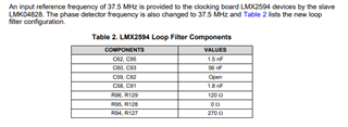
    If I'm understanding correctly, it is 33.75 MHz as per Table 2 on page 7 of https://www.ti.com/lit/ug/tidud80a/tidud80a.pdf.  33.75 MHz seems pretty close to 37.5 MHz for purposes of general optimization.

    So no need to respond to my previous message about SDCLK issues (assuming LVDS format will be okay).

    Great.

    73,
    Timothy

  • Hi Timothy,

    Thank you for the response.

    I am still going through TI Designs: TIDA-01023 trying to modify the provided firmware for my application.

    So far, I've successfully modified "1023_LMK04828EVM_Master_3GREF_300MOut_37.5MSync_Output_Distribution.tcs" to use a 2 GHz reference and provide a 200 M Out and a 25 MHz pulsed Sync.

    Now I am trying to modify the firmware for my TIDA-01021-E2 boards referenced on page 12 and 13 of the design document:
    "1023_BRD1_LMK04828_300MREF_300MFCLK_37.5MSYSREF.cfg"
    "1023_BRD1_LMX2594_A_B_3GCLK_37.5MREF_37.5MPFD.cfg"

    I am using "High Speed Clocking and Data acquisition TIDesigns GUI v1.1.2" to modify these firmware files.

    Using this firmware as is gives me a 2 GHz CLK and a 25 MHz REF, due to using the same dividers with a reduced input reference frequency. I would like to get a 10 MHz REF out, instead of 25 MHz, but when I increase the SYSREF DIV from 8 to 20 the REF out frequency becomes about 11.36 MHz instead of 10. I need to increase the SYSREF DIV to 23 to get a 10 MHz REF. Any idea why this could be happening?

    Also, I noticed that when I change the divider value, the output phase of the REF from the two LMX2594 shifts, resending sync pulses from the master LMK doesn't realign their phase. Is this to be expected?

    Thank you,

    Alex

    1023_BRD1_LMK04828_300MREF_300MFCLK_37.5MSYSREF.cfg1023_BRD1_LMX2594_A_B_3GCLK_37.5MREF_37.5MPFD.cfg

  • Is it possible that I need to adjust the slave LMK firmware to accept the LVDS pulsed sync signal? Looking at the differential sync pulses straight out of the master LMK board, each arm of the differential signal is swinging between about 500 mV to 800 mV, so a Vcm of about 650 mV.

  • Okay, I see now that 23 is the correct value for SYSREF_DIV to get 10 MHz because (SYSREF_DIV)*2+4 is actually how much it is dividing by. Still not sure how to adjust the relative phase of the low frequency outputs from the LMX2594s after adjusting the dividers.

  • Seems like the purpose of the SYSREF in this this design may just be to clock the writing of the firmware to the ADCs. Perhaps adjusting their relative phase isn't important. What is important is synchronizing the SYSREF to the FPGAs and I think those come straight from the LMK on the clocking board. Can't view those signals directly with my equipment easily since they are distributed to the FPGAs through samtec connectors.

  • Alex,

    Apologies for the delay, Timothy is OoO and will return on Monday.

    Regards,

    Derek Payne

  • Hi Alex,

    As you are planning to use same configuration files as per your TIDA-01021 JMODE0 (config files present in first thread) with TIDA-01023 setup (multi-board synchronization). You need to have your SYSREF from first LMK should be 10MHz, as it is your required SYSREF frequency for JMODE0 with "JESD IP Core_K" value 10.

    Modified LMK04828 TICS Pro files are attached along with configuration file for your application.

    You can use the your existing config file of LMX2594 for this setup. But before this you need to write few registers in each secondary board LMK (same settings present in first few lines in 1023_BRD1_LMX2594_A_B_3GCLK_37.5MREF_37.5MPFD.cfg);

    LMK04828
    0x137 0x04
    0x144 0xFF
    0x139 0x03
    0x143 0x50

    1023_LMK04828EVM_Master_2GREF_200MOut_10MSync_Output_Distribution.tcs

    1021_LMK04828_200MREF_200MFCLK_10MCLK_10MSYSREF_Distribution.tcs

    1021_LMK04828_200MREF_200MFCLK_10MCLK_10MSYSREF_Distribution.cfg

    4276.1023_BRD1_LMX2594_A_B_3GCLK_37.5MREF_37.5MPFD.cfg

    While using these updated files, you need to follow the TIDA-01023 programming steps for synchronizing multiple TIDA-01021 boards.

    Hope, this will resolve your clock synchronization issue.

    Regards,
    Ajeet Pal

  • Hello Ajeet,

    I should have mentioned that we would like to operate in JMODE2 now.

    You can use the your existing config file of LMX2594 for this setup.

    Great. To be sure, are you referring to the 1021_JMODE0_LMX2594_A_B_2GCLK_10MREF_10MPFD.cfg file you previously provided us? Will this work as is for JMODE2?

    Thank you,

    Alex

  • Hi Alex,

    The difference between JMODE0 and JMODE2 is, ADC is operating in single channel and dual channel mode respectively. Hence the clocks should be same for both the modes. The existing frequency setting for JMODE2 will be valid withr  "JESD IP Core_K" value 10 same as you were doing for JMODE0.

    Alex Wargo said:
    Great. To be sure, are you referring to the 1021_JMODE0_LMX2594_A_B_2GCLK_10MREF_10MPFD.cfg file you previously provided us? Will this work as is for JMODE2?

    Yes, the existing configuration file for LMX2594 will work for JMODE2.

    Regards,

    Ajeet Pal