This thread has been locked.

If you have a related question, please click the "Ask a related question" button in the top right corner. The newly created question will be automatically linked to this question.

Simulating .cir file in PSpice for TI

Other Parts Discussed in Thread: LM5176

Hi,

I would like to simulate .cir file directly using PSpice for TI. User's manual mentions batch simulation but user's manual that came with PSpice apparently describes some older version. So how çir file can be simulated directly? 

Thanks!

Regards

Goran

  • Hi Goran,

    Would  you please point me to the user's manual where it shows an older version of PSpice?

    Thanks,
    JC

  • Hi JC,

    Check the page 461. There is description on how to set up a batch mode simulation. One of the steps is:"Select Open Simulation from the file menu from PSpice window".. In FIle menu I can only open Project, Design or txt file. Also PSpice simulation window on figure 8-1 looks differently from the window I see when I start PSpice for TI. 

  • Hi JC,

    OK, I managed to get to PSpice window and to load cir file. However, when I start simulation I get the following error:

    ERROR(ORPSIM-16551): Floating point computation failed during Device/Model Load. Possible solutions: 1)Ensure that all device parameters are in valid range. 2)Try using .options LIMIT

    INTERNAL ERROR -- Overflow in device XU1.D_VCC_REG_D10, Divide

    I am simulating a power supply built around LM5176P. I double-checked circuit connections and found nothing suspicious. Any idea why this might be happening.

    Regards

    Goran

  • Hi Goran,

    This could be due to extreme value of certain component parameters. Please set the LIMIT option to something like 1E12:

    .OPTIONS LIMIT= 1E12

    Thanks,
    JC

  • HI JC,

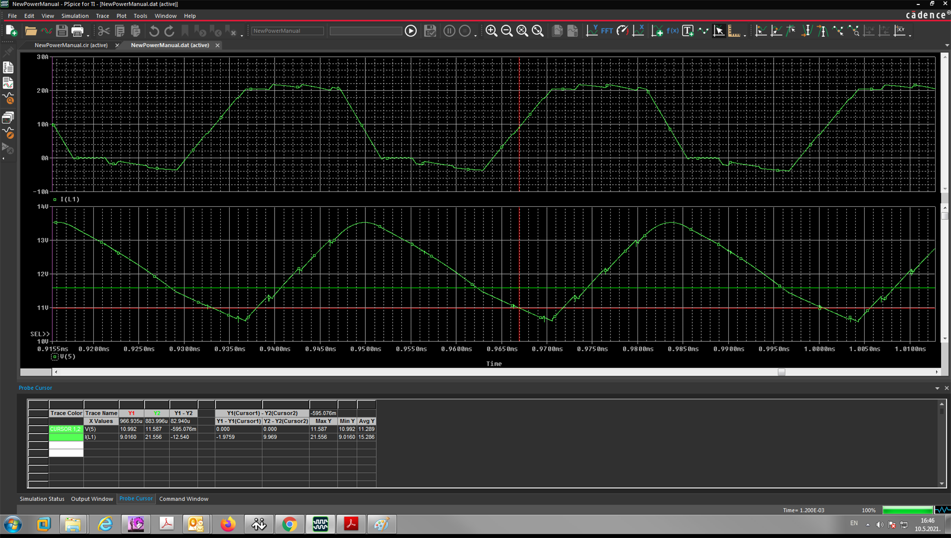
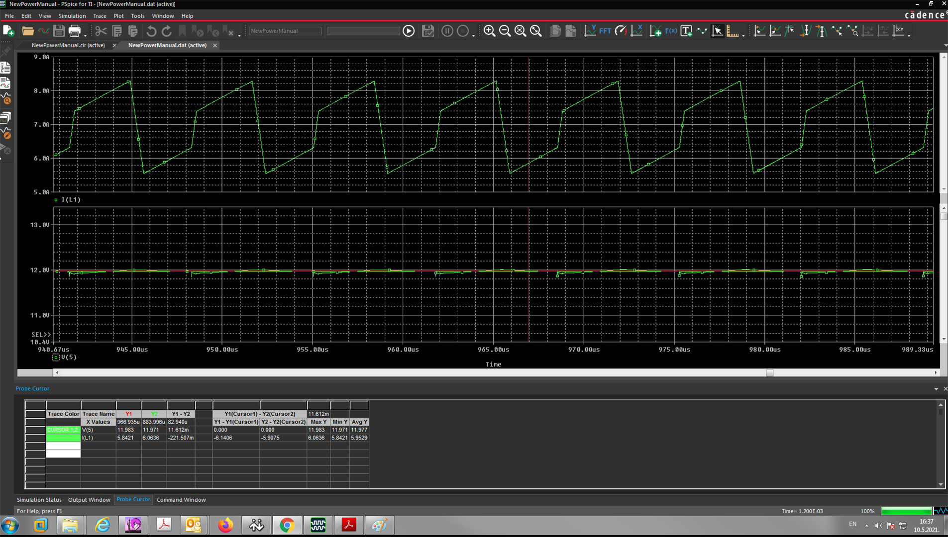
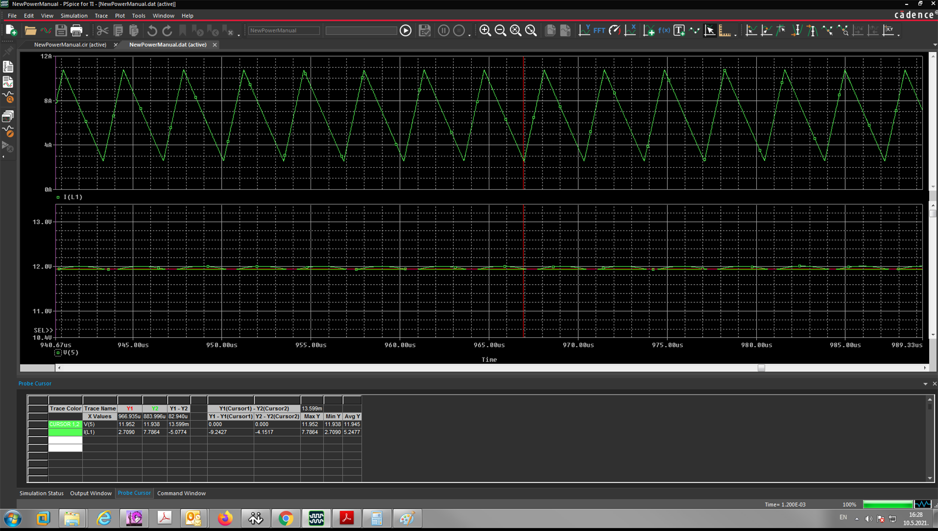
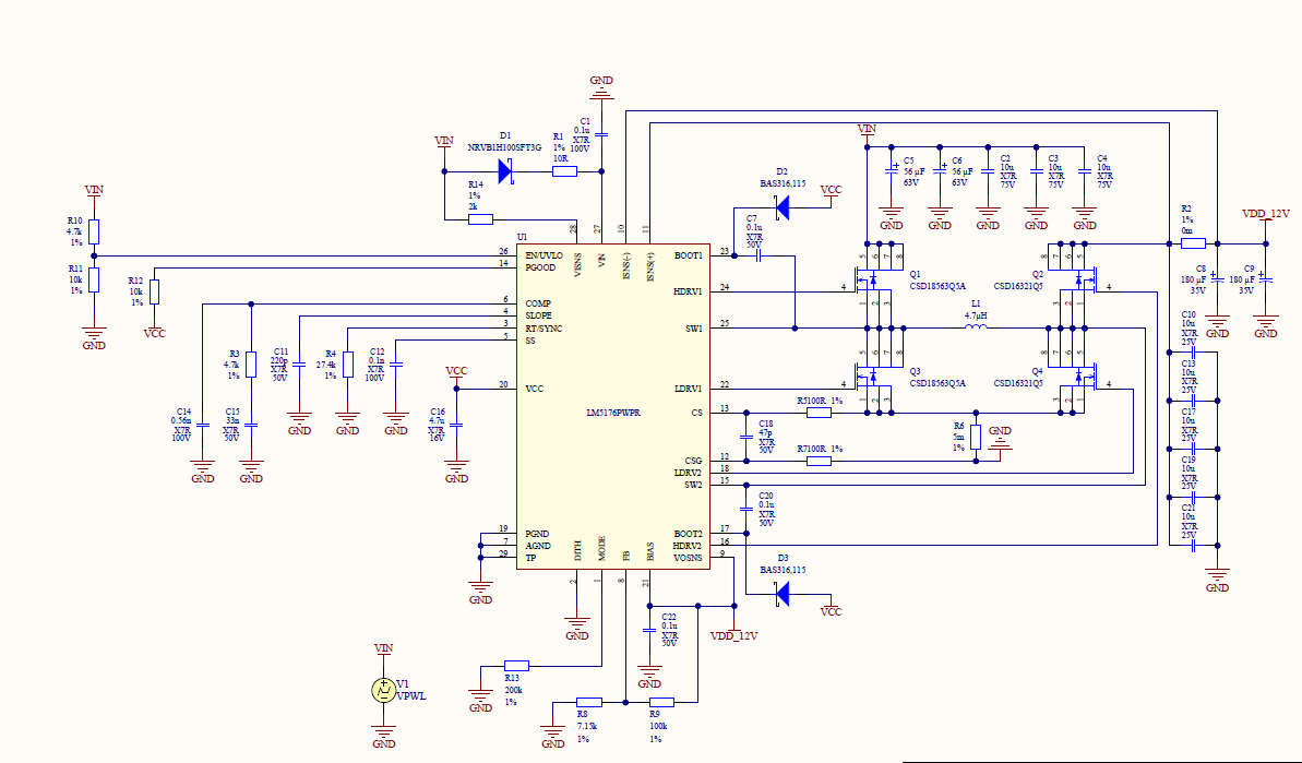
    With some tweaking I managed to finally simulate the circuit. The idea is to have power supply capable of working with input voltages from 4.2 vto 55V providing 6.7A at the output. I attached schematics of the circuit. In "Buck" mode circuit apparently works fine. Figures 2 and 3 show output voltage and inductor current for input voltages of 36V and 13V. However, in "Boost" mode circuit does not work as expected. Figure 4 shows output voltage and inductor current for input voltage of 11V (First attached image is fig. 4, than fig. 3 and fig. 2). Internal resistance of the voltage source that provides power to the circuit is set to 50u so it is practically an ideal voltage source. Any idea what may be wrong with "Boost" mode?

    Regards

    Goran

  • Hi Goran,

    A product expert will be helping you out.

    Thanks,
    JC

  • Hello Goran,

    Why do you think that the part is not working as expected? It seems to me that the output voltage is regulated to the level you want to have, right?

    How about checking out the EVM of the LM5176?

    Best regards,
    Brigitte

  • Hi Brigitte,

    In the first attached image bottom green trace represents output voltage (Boost mode). It goes from about 10.6V to 13.5V (it shoud be 12V). So the ripple is pretty high whereas in "Buck" mode (next two images output voltage ripple is in range of few tens of mV). So the "Boost" mode doesn't not look good. Also, the voltage ripple frequency is about 200kHz while device switching frequency is set to 300k.

    Regards

    Goran

  • Hello Goran,

    What happens if you reduce the capacitor on the SLOPE pin?

    Best regards, 

    Brigitte 

  • Hi Brigitte,

    I have just found what was wrong! Schematic from which I generated netlist file and finally "cir" simulation file had lowercase Greek letter 'µ' used for marking "microfarads" on input and output capacitors (instead of lowercase 'u'.). It was hard to spot this since these two letters are almost indistinguishable when used inside an ASCII file. I replaced 'µ' with 'u' and circuit now works fine.

    Regards

    Goran

  • Hello Goran,

    Thank you very much for the update.

    Have a good weekend,
    Brigitte