


Other Parts Discussed in Thread: ADS1118, TIDA-00483
Hi , We are going to design a hardware for "Loop-Powered, 4- to 20-mA Field Transmitter With HART Modem" . I was reading the Demo version released by TI named " TI Designs: TIDA-01504 Highly Accurate, Loop-Powered, 4- to 20-mA Field Transmitter With HART Modem Reference Design . I have few question hope someone can give a satisfying answer
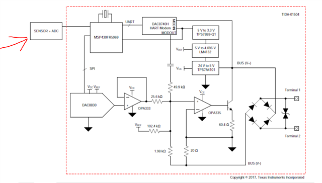
1. In the block diagram , as we can see "Sensor+ADC" block is to interface with Demo board externally . I cannot see any connector on the schematic of this Demo. At which point in the Demo board the ADC output can be connected? In the Demo reference manual , I cannot find the explanation of this part like what kind of sensor and ADC can be interfaced and what are requirements?
2.Can you recommend some other Demo board which include SENSOR+ADC+MSP430+HART&DAC +LOOP POWER CIRCUITRY
3.If there is no such Demo board then can you recommend me some ADC which i can add in hardware design of above Demo ?
Thanks

