


Other Parts Discussed in Thread: BQ76200
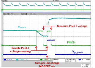
n this design, standby mode refers to two kind of scenarios: when the battery pack is outside of the e-bike and when the battery pack is put inside of the e-bike but not running. Because this design is for using the same charge and discharge port, the charger is only attached in the first scenario. The battery pack in the first scenario should be able to detect if the charger is attached or if the battery pack is put inside of the ebike. The battery pack in the second scenario should be able to detect if load is on or if the battery pack is plugged in outside of the e-bike. Figure 27 shows the standby test waveforms in the first scenario. The dark blue curve is the pre-discharge MOSFET drive voltage and the green curve is PMON of the BQ76200, which controls a switch to measure PACK side voltage. The light blue curve is the PACK side voltage. The first pulse of PMON is to measure PACK voltage with pre-discharge MOSFET off. If the charger is attached, the voltage should be equal to 54.6 V. If not, the pre-discharge will be turned on. After a short time delay, the PACK voltage will be measured again. If the battery pack is put in the e-bike, a large capacitor will be connected between PACK+ and PACK-, therefore, the measured voltage is lower than the battery voltage. Otherwise, the PACK voltage is equal to the battery voltage. The detection sequence happens every 200 ms, which will not cause obvious delay.
If the charger is attached, the voltage should be equal to 54.6 V. i think the voltage not the charger voltage (54.6V), it should be battery voltage.
can explain this passage in detail? i understand, first judge if connect the charger? why the BQ76200 measure voltage is charger voltage not battery voltage. and then judge if connect the load, but not runing.
why the Vpack+ voltage rise? when the second pulse, let pre-discharge MOSFET on, the waveforms as follows:
In the second scenario, the predischarge MOSFET is mostly on. If load is on, there will be a voltage drop across the resister series with the pre-discharge MOSFET, therefore, the measured voltage is lower than the battery voltage. If not, the pre-discharge will turn off. After a some time delay, the PACK voltage is measured. If the battery pack is plugged outside of the e-bike, the output capacitor is much smaller, which will cause a larger voltage drop. The waveforms are shown in Figure 28
i do not understand:
If the battery pack is plugged outside of the e-bike, the output capacitor is much smaller, which will cause a larger voltage drop.
the battery outside the e-bike or inside the e-bike? output capacitor comes from where? why cause a large voltage drop?
