This thread has been locked.

If you have a related question, please click the "Ask a related question" button in the top right corner. The newly created question will be automatically linked to this question.

TIDA-01513: capacitors between HV and chassis ground

Part Number: TIDA-01513

Hi,

Customer had a question for this design. It mentions in the image below that it can be complex to calculate the isolation leakage due to capacitors between HV and chassis and the customer will likely have 2uF y-capacitors between busbar and ground. Could you please advise how the procedure or calculations change in this case? What is the best way for them to determine the leakage resistance?
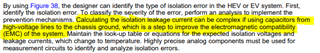
Thanks!

  • Hi Aivaras,

    The capacitors in the circuit will affect the time the output voltage amplifiers reach a steady voltage. The reason for that is when the switch is turned on, it needs power to charge the capacitors.

    I made a simply simulation to clarify this. You can see the simulation in Fig.1 and Fig.2, the steady voltage is the same, but you can see a tiny voltage drop before the output voltage becomes steady.  

    Fig.1 The simulation without the Capacitors

    Fig.2 The Simulation with the Capacitors

    Above all, if you can tolerate the time to be steady, the calculation is the same. 

    Thanks,

    Anna