This thread has been locked.

If you have a related question, please click the "Ask a related question" button in the top right corner. The newly created question will be automatically linked to this question.

TIDA-01606: How to use SVPWM for 6 switch PFC

Part Number: TIDA-01606

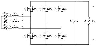
Hello there, We are going to design 24 KW 6 switch bidirectional PFC so that in the TIDA-01606 ref design there is a SVPWM function that TINV_updateSVPWM(TINV_vInv_dq0.a, TINV_vInv_dq0.b,TINV_vInv_dq0.c);

I want to use this function in ref design of lab7, could you help us how to use SVPWM function for 6 switch pfc..

  • Dear Sadik,

    The function TINV_updateSVPWM is a function that do the following things:

    • take the index modulation
    • find max and min
    • calculate the third harmonic injection value
    • add the third harmonic injection value to all the existing modulation indexes
    • Index modulation are scaled in duty cycles
    • update the registers for giving the right duty cycles.

    In existing LAB 7 reference design I am seeing these things:

    • Calculate PI control for D and Q loops.
    • Obtain Per unit VD and VQ values out of the control loops
    • Apply the rotation and alpha beta transformation. You obtain back three values for each leg of the line. In the code is written duty cycles but these can be considered as index modulation. 
    • Index modulation are scaled properly in duty cycle values and update the registers.

    Comments about LAB 7 design:

    Based on this description and comparison of the codes, I would like to ask you the sequent questions so in this way I can address properly the answer:

    • Would you like to have in the code the third harmonic feature?
    • Is it a problem for you the index and duty cycle convection?
    • Is there anything not clear in which way the registers for the two functions are updated?
    • Is your topology a standard 2-Level six switch PFC?

    Many thanks for your attention

    Best Regards

    Riccardo

  • Topology is a standart 2-Level six switch PFC as added picture.

    I would like to have in the code the third harmonic feature for 6 switch PFC.

    what is the mean differance between index modulation and third harmonic , may I use index modulation for 24 KW PFC which one is better for this high power aplication.

    ıt is not clear that how to apply TINV_updateSVPWM function for 2 level 6 switch PFC.

  • Hi Sadik,

    third-harmonic injection is a feature that allows you, by having the same DC bus voltage, to achieve higher controllability range.

    Three important features are present when this method is used:

    • control loops have more controllability range;
    • you work more linear when the voltage of DC bus is set to a lower value;
    • DC bus voltage can be decreased more with respect a case where you do not have this feature.

    In conclusion, by having the third-harmonic injection mostly you just add advantages in the system so typically I recommend this feature. 

    Related to your application I think that it is a good idea to use part of the function TINV_updateSVPWM until the moment that duty cycles are calculated. So I mean:

    • take the index modulation
    • find max and min
    • calculate the third harmonic injection value
    • add the third harmonic injection value to all the existing modulation indexes

    After that you have these duty cycles you should re-scale in order to achieve a per unit value between 0 and 1 and update the proper registers with the proper values.

    I hope that I have fully answered your questions.

    Best Regards

    Riccardo

  • static inline void TINV_updateSVPWM(float32_t ma,
    float32_t mb,
    float32_t mc)
    {
    float32_t mx;
    float32_t mn;
    float32_t md;
    float32_t mcm;

    float32_t d11;
    float32_t d14;
    float32_t d21;
    float32_t d24;
    float32_t d31;
    float32_t d34;

    //
    // Finding max amongst 3
    //
    if ((ma > mb) && (ma > mc))
    {
    mx = ma;
    }
    else if (mb > mc)
    {
    mx = mb;
    }
    else
    {
    mx = mc;
    }

    //
    // Finding min amongst 3
    //
    if ((ma < mb) && (ma < mc))
    {
    mn = ma;
    }
    else if (mb < mc)
    {
    mn = mb;
    }
    else
    {
    mn = mc;
    }

    //
    // Calculating mid
    //
    md = -(mx + mn);

    //
    // Identification of subsectors and sub-subsectors
    //
    if (mx - mn <= 0.5f)
    {
    //
    // subsector = 1;
    //
    if (md > 0)
    {
    //
    // Subsector 1b
    //
    mcm = mx * 0.5f;
    }
    else
    {
    //
    // Subsector 1a
    //
    mcm = mn * 0.5f;
    }
    }
    else if ((mx - md <= 0.5f) && (md - mn <= 0.5f))
    {
    //
    // subsector = 2;
    //
    if (md > 0)
    {
    //
    // Subsector 2b
    //
    mcm = (mn + 0.5f) * 0.5f;
    }
    else
    {
    //
    // Subsector 2a
    //
    mcm = (mx - 0.5f) * 0.5f;
    }
    }
    else
    {
    //
    // Subsector 3 and 4
    //
    mcm = md * 0.5f;
    }

    TINV_duty_A_pu = (ma + mcm);
    TINV_duty_B_pu = (ma + mcm);
    TINV_duty_C_pu = (ma + mcm);
    TINV_mcm = mcm;
    //
    // Assigning the duty ratios
    //
    if (ma + mcm > 0)
    {
    d11 = (ma + mcm);
    d14 = 0;
    }
    else
    {
    d11 = 0;
    d14 = -(ma + mcm);
    }

    if (mb + mcm > 0)
    {
    d21 = (mb + mcm);
    d24 = 0;
    }
    else
    {
    d21 = 0;
    d24 = -(mb + mcm);
    }

    if (mc + mcm > 0)
    {
    d31 = (mc + mcm);
    d34 = 0;
    }
    else
    {
    d31 = 0;
    d34 = -(mc + mcm);
    }

    EPWM_setCounterCompareValue(TINV_Q1_Q3_A_PWM_BASE,
    EPWM_COUNTER_COMPARE_A,
    (uint32_t)((float32_t)(TINV_PWM_PERIOD_TICKS / 2.0) * fabsf(d11)));

    EPWM_setCounterCompareValue(TINV_Q2_Q4_A_PWM_BASE,
    EPWM_COUNTER_COMPARE_A,
    (uint32_t)((float32_t)(TINV_PWM_PERIOD_TICKS / 2.0) * fabsf(d14)));

    EPWM_setCounterCompareValue(TINV_Q1_Q3_B_PWM_BASE,
    EPWM_COUNTER_COMPARE_A,
    (uint32_t)((float32_t)(TINV_PWM_PERIOD_TICKS / 2.0) * fabsf(d21)));
    EPWM_setCounterCompareValue(TINV_Q2_Q4_B_PWM_BASE,
    EPWM_COUNTER_COMPARE_A,
    (uint32_t)((float32_t)(TINV_PWM_PERIOD_TICKS / 2.0) * fabsf(d24)));

    EPWM_setCounterCompareValue(TINV_Q1_Q3_C_PWM_BASE,
    EPWM_COUNTER_COMPARE_A,
    (uint32_t)((float32_t)(TINV_PWM_PERIOD_TICKS / 2.0) * fabsf(d31)));
    EPWM_setCounterCompareValue(TINV_Q2_Q4_C_PWM_BASE,
    EPWM_COUNTER_COMPARE_A,
    (uint32_t)((float32_t)(TINV_PWM_PERIOD_TICKS / 2.0) * fabsf(d34)));

    }

    for 6 switch pfc I just need 3 duty cycle value but in the function there is 6 differance value., how to find duty_A, duty_B,duty_C for SVPWM.

  • Hi Sadik,

    the index modulation that must be applied by the converter are the sequent:

    TINV_duty_A_pu = (ma + mcm);
    TINV_duty_B_pu = (ma + mcm);
    TINV_duty_C_pu = (ma + mcm);

    Best Regards

    Riccardo

  • Hı,

    TINV_duty_A_pu = (ma + mcm);
    TINV_duty_B_pu = (mb + mcm);
    TINV_duty_C_pu = (mc + mcm);

    is this one currect or

    TINV_duty_A_pu = (ma + mcm);
    TINV_duty_B_pu = (ma + mcm);
    TINV_duty_C_pu = (ma + mcm);

    because each of duty cycle must be difference

  • Hi Sadik,

    you are right.
    Best Regards

    Riccardo