This thread has been locked.

If you have a related question, please click the "Ask a related question" button in the top right corner. The newly created question will be automatically linked to this question.

Sensor to get speed of a scooter.

Other Parts Discussed in Thread: TMAG5110, TMAG5111, DRV5032

I need to get the speed of an e-scooter and display it on an LCD screen together with battery level and light ON/OFF. Which hall sensor or optical sensor can be used to detect speed of the moving scooter? Also how can a TIDA 00449 BMS be interface to a microcontroller together with the sensor reading and be displayed on the LCD?

Thank you.

  • Desieah,

    There are a few options you might consider.  If using a single diametric ring magnet embedded into the wheel of the scooter, it would be possible to track speed and direction of rotation using a device like TMAG5110 or TMAG5111.  These devices are capable of detecting two axes of magnetic field and can track the quadrature of the field for this purpose.  It would be similarly possible to just place a magnet on the wheel somewhere it is able to pass by a hall effect switch like DRV5032.  Every time the magnet passes by the output will toggle momentarily.  Speed could then be calculated by counting pulses.  For better resolution, multiple magnets could be inserted to the wheel.

    For the TI Design, it appears that it is controlled using an MSP430.  I would expect that using this design, one might be able to create custom firmware to send the readings to your LCD.  The firmware is available for download here: https://www.ti.com/lit/zip/tidcbb1

    Thanks,

    Scott

  • Thank you very much for your reply.

    I actually need to get the battery level from the BMS(TIDA 00449 board) and send it to an msp430 microcontroller and display it on the screen. Is it possible to get this data (battery level) from the TIDA 00449 board and through which pins can i send it to the msp430.

  • Dosieah,

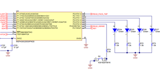
    The gauging algorithm running on U3 (MSP430) of TIDA 00449 is driving IOs which are connected to the 4 indicator LEDs.  In the schematic these appear to be pins 9-12 of U3.

    These follow the logic here:


    To implement your own algorithm, it would be necessary to create a new firmware for the onboard MSP430 or to find a way to bypass it by replacing the connections to the various control lines shown.

    The complete schematic is available for download here:

    https://www.ti.com/lit/pdf/tidrht7

  • Thank you very much for your reply. It is very helpful. Will try editing the firmware.